
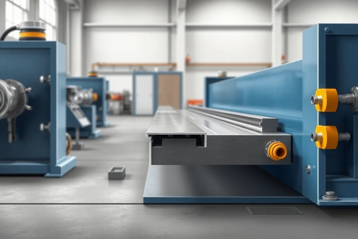
A steel door threshold is the horizontal transition at a floor opening. It is not a simple bar stock or a bent channel. The profile must bridge between two floor conditions, present a controlled contact surface for the door leaf or its bottom seal, accept fasteners, and tolerate repeated foot traffic. In roll forming, a flat steel strip is progressively bent through a series of contoured stations until it becomes that threshold section. The machine that does this work is a steel door threshold roll forming machine. It combines coil handling, strip feeding, feature punching, progressive forming, cutoff and often secondary assembly of end caps or seal carriers.
This page explains the section geometry, the interfaces the threshold must satisfy, how steel roll forming differs from aluminum extrusion and from jamb production, and what a buyer should specify when defining a new profile or an additional size. Start with the profile drawing, material, required features and complete assembly scope, then define the tooling and acceptance checks around those inputs.
Threshold role and section definition
A threshold section is best understood as a set of functional zones along one continuous profile. The outermost edge meets the exterior or corridor floor finish. The inner edge meets the interior floor. Between them, a raised or stepped region provides the door leaf contact and the seal landing. A vertical return or leg may conceal the floor edge, while one or more horizontal flanges carry fasteners into the floor or subframe.
Unlike a simple angle or channel, a threshold usually has more than one plane change. The profile may rise to a contact land, step down to a seal groove, and turn again into a screw flange. Each of these changes is a bend line that must be placed in the correct sequence. The section definition therefore includes bend angles, leg heights, flat widths, inside radii, material thickness and the position of any holes or notches relative to the bend lines. Without a dimensioned section drawing, the roll forming stations cannot be designed or validated.
The door threshold is frequently confused with the jamb or frame profile. A jamb is a vertical or head section that receives the door in its closed position. A threshold is horizontal and primarily resolves the floor junction, the bottom seal and the traffic surface. They may share material and coating, but their forming sequences, cutoff requirements and handling risks are different, and a line configured for one should not be assumed suitable for the other.
Floor, door leaf and seal interfaces
The floor interface is not one condition. A threshold may sit over a concrete slab, a timber subfloor, a metal pan, a raised access floor or a transition between two finish materials. The underside of the profile must sit flat enough to avoid rocking, and the fastener flanges must be wide and accessible enough for the specified fixing. If a hollow leg is intended to cover an uneven floor edge, the leg depth and open side must be defined in the drawing rather than left to site trimming.
The door leaf interface is the contact surface where the leaf or its bottom seal rests. That surface must be wide enough to accept the seal without overhang, and it must be positioned at the correct height relative to the frame. The seal interface may be a simple flat land, a shallow groove that retains a gasket, or a slot that accepts a push-in carrier. The forming operation must produce that retention feature without work-hardening the strip to the point of cracking or distorting the adjacent flat.
Because the floor, leaf and seal requirements are project-specific, buyers should state them as assembly requirements: contact width, seal type, fastener style, exposed finish and maximum permitted gap or step. The machine does not decide these values. It forms the section that the drawing defines, and acceptance is judged against that drawing and the specified assembly.
Steel strip forming versus extruded profiles
Aluminum extrusion is produced by pushing heated metal through a die, which can accommodate suitable constant sections with features that differ from bent-strip geometry; feasibility still depends on the alloy, die and section. Steel roll forming, by contrast, starts from thin strip and creates the section by bending. It is generally well suited to open, constant-section profiles with moderate flange widths, consistent material thickness and moderate bend complexity. It cannot create enclosed cavities in one pass without separate closing operations or welded or fastened sub-assemblies.
The economic comparison depends on volume, tolerance and finish. Extrusion tooling usually involves a die and a press, while roll forming requires a set of contoured rolls matched to the section. For long runs of a stable steel profile, roll forming often provides good repeatability from coil to coil and can integrate punching and cutoff in line. For short runs, frequent design changes, or profiles with deep returns and closed sections, extrusion or a fabricated assembly may be more practical. The two routes also differ in surface appearance: extruded aluminum can be anodized with a uniform finish, while steel roll forming relies on the coated or plated strip and on how carefully the rolls and handling equipment protect that surface.
A third route is press braking from sheet. It offers flexibility for low volume and prototypes while roll forming can integrate repeated section production and features for sustained runs. Compare demonstrated tolerances, handling and cost for the actual section rather than assuming one route always gives better accuracy. The right choice is a function of profile geometry, annual quantity, finish requirement and acceptable unit cost.
Material, coating and exposed surfaces
Threshold strip is typically specified as coated steel, stainless steel or another alloy. The buyer defines the base-metal grade and thickness, and the supplier confirms whether the proposed tooling and forming sequence can run that combination without unacceptable marking or cracking. Thickness is a selection requirement rather than a machine rating: a line may be designed or adjusted for a range, but the actual working range must be verified for the specific profile.
Exposed surfaces matter because a threshold is visible and touched. Common finishes include galvanized or zinc-coated steel with a paint or laminate system, and stainless steel with a brushed or polished face. The forming process can mark the strip through roll contact, guide friction or handling after cutoff. Protection may include protective film, roll materials and finishes selected to reduce marking, and careful packing. The acceptance check is not simply the coil certificate; it is the condition of the finished part after forming, cutoff, any secondary operations and packing.
Progressive step and return forming
In progressive roll forming, the strip passes through a series of stations. Each station performs a partial bend, and the cumulative effect produces the final section. A threshold with a central step and two returns might be sequenced so that the outer edges are pre-bent first, the step is raised in stages, and the return legs are closed toward the end. The exact sequence depends on bend angle, material thickness, inside radius and the need to avoid stretch or buckle in adjacent flats.
Step and return features are the most sensitive parts of threshold tooling. A sharp inside radius on thick strip can concentrate strain and lead to cracking, especially in high-strength or low-ductility material. A heavily stepped profile can also cause the strip to twist if left and right bends are not balanced. The roll designer will usually adjust the number of forming stations, the amount of bend per station and the use of idle or side rolls to control the section. Buyers should include the profile drawing and material condition in the enquiry so that the proposed process route can be assessed, rather than treating the forming sequence as a fixed catalogue item.
Holes, drainage features when specified and cutoff
Thresholds often require fastener holes, counterbores, notches for frame intersections or drainage features. Punching can be performed in line before or during forming, or off line as a secondary operation. Choose punching sequence by final datums, tool access and trial evidence; integration alone does not establish better positional accuracy near a bend. If holes are punched before forming, the tooling must account for the change in position as the material bends. Drainage slots or weep features, when specified, should be defined by the drawing and confirmed as compatible with the forming sequence and with the intended assembly.
Cutoff is the final separation of the finished section from the strip. The cutoff tool must support the profile so that the cut end is clean and square. Some profiles require a die that follows the section shape; others can be cut with a shear or saw arrangement. The buyer should state cut lengths, permitted end conditions and whether any secondary operation, such as deburring or end forming, is needed. Include profile-supported cutoff, cut lengths, end quality and any secondary operations in the process brief.
Profile variants and tooling access
Threshold profiles vary by contact geometry, step height, flange width, seal retention and exposure. A shallow transition for an interior opening may use a simple stepped section, while an exterior threshold may require a deeper body, a wider seal land and a more robust fastening flange. Variants can often share a machine base and some stations, but the roll set, punch tooling and cutoff die are profile-specific. A change in material thickness or base-metal grade may also require tooling validation.
Tooling access is a practical constraint. Rolls need to be reachable for setting, cleaning and replacement, and the cutoff area needs enough clearance for the section and any scrap. If a future variant is planned, the buyer should discuss whether the machine frame, drive and control can accept additional stations or a different roll set. This is a planning question, not a guarantee: the supplier must confirm the actual capacity against the proposed profiles.
End caps, seals and assembly scope
A formed threshold may be supplied as a bare cut length or as an assembled component. End caps close the open ends of the section and improve appearance and handling. Seals may be inserted into a groove or carrier after forming. Assembly may also include corner pieces, splice plates or fastener hardware. The scope of supply should be explicit: does the machine include the sealing or cap insertion equipment, or is that a manual or separate operation?
If assembly is part of the production cell, the component feeding method, orientation and cycle time must be considered alongside the forming rate. A line that forms quickly but requires manual assembly may not meet the required output. The output target should therefore be defined in accepted finished assemblies per shift, using the actual profile and material, not as a generic speed figure.
Fit, finish and handling acceptance
Acceptance should be based on the finished part and the specified assembly. The following checklist covers the main points. It is a practical guide, not a substitute for the drawing and the agreed inspection plan.
- Section dimensions: bend positions, leg heights, flat widths and step height within the drawing tolerance.
- Straightness and twist: check over the full cut length, not only at the ends.
- Holes and features: position relative to a datum bend, diameter, and absence of distortion around the hole.
- Cut ends: squareness, burr condition and any required deburring.
- Surface: coating or finish condition after forming and handling, including marks from rolls or guides.
- Seal fit: trial assembly of the specified seal or carrier where applicable.
- Fastener fit: trial fixing into the flange with the specified fastener.
- End caps or assembly: fit and retention if supplied as part of the scope.
Handling and packing also affect acceptance. Formed thresholds can be scratched or bent after cutoff, so the route from the line to the pack should be defined. A sample inspection plan should state sample size, frequency and the person responsible for each check. Determine whether holes, notches or drainage details are made in line or separately, inspect cut ends and the installed seal fit, and assess surface protection on the finished part after handling and packing.
Production brief
A useful production brief for a steel door threshold roll forming machine brings together the section drawing, the material and thickness specification, the required features and their positions, the cut lengths, the finished assembly scope, the output target and the electrical supply. These are selection requirements that the buyer defines and the supplier confirms against the proposed equipment. The brief should distinguish between what is fixed by the building design (interfaces, finish, fastener type) and what can be adjusted by tooling or process (forming sequence, station count, cutoff method). It should also state the acceptance checks clearly, so that the first article and production parts are judged consistently.
FAQ 1: How does a steel door threshold roll forming machine differ from a jamb roll forming line?
A threshold line is arranged around a horizontal section that resolves the floor junction, the door leaf contact and the seal landing. A jamb line is arranged around a vertical or head section that receives the door and often has a different bend sequence and cutoff requirement. They may share a machine platform, but the roll tooling, punch tooling and cutoff die are profile-specific. A line configured for one should not be assumed to produce the other without a tooling and process review.
FAQ 2: Can the same machine run stainless steel and coated carbon steel?
Possibly, but not automatically. Stainless steel and other alloys can have different forming behaviour, springback and surface sensitivity compared with coated carbon steel. The buyer should specify the material and grade, and the supplier should confirm whether the proposed roll set, lubrication, guide materials and handling method are suitable. Separate tooling validation is often needed for a different alloy, and the operating range must be verified for the actual profile.
FAQ 3: Are drainage holes and seal grooves made in line or as a secondary operation?
Either is possible. Punching or notching before or during forming can hold position relative to a bend, but the tooling must account for material movement during bending. Features made after forming may be simpler in some cases but can disturb the section or the coating. The right answer depends on the feature geometry, tolerance and volume. The buyer should state which features are required and ask the supplier to confirm whether they are made in line or separately, and how their positions are verified.
FAQ 4: What should be specified for cutoff and end quality?
Specify the cut lengths, the tolerance on length, the required end squareness, the acceptable burr condition and whether deburring or end forming is needed. The cutoff tool must support the profile so that the section does not collapse or distort. Some profiles need a shaped die or a follow-on cutting action. The process route should state whether cutoff is integrated with the line or performed separately, and acceptance should include a check of the cut ends on the finished part.
FAQ 5: How is surface finish controlled on exposed threshold faces?
Surface finish is controlled through the strip specification, the roll and guide materials, the forming sequence, lubrication and handling after cutoff. Protective film may be used, but it must be compatible with the forming process and removable without residue. Acceptance should assess the finished part after forming, cutoff, any secondary operations and packing, not only the incoming coil. The buyer should define the visible faces and the acceptable condition, and the supplier should confirm how those faces are protected through the line.

Continue your research
- Door & Window Profile Roll Forming Machines
- Steel Door Frame Roll Forming Machine
- Window Frame Roll Forming Machine
- Hollow Metal Door Frame Roll Forming Machine
- Garage Door Track Roll Forming Machine
- Door Reinforcement Channel Roll Forming Machine
- How Door frame roll forming machine Works
- How To Choose a Door frame roll forming machine
- Door frame roll forming machine Price: What Affects the Cost?
Configuration & specification inputs
Match the configuration to your section drawing, material and production requirements.
| Parameter | Requirement / confirmation needed |
|---|---|
| Profile geometry | A threshold must meet the door seal and floor interface. Review its exposed finish, drainage detail and corner geometry rather than treating it as a generic channel. |
| Material | Specified sheet steel; stainless or other alloys need separate tooling validation |
| Thickness & grade | Buyer to specify base-metal thickness and grade; operating range requires supplier verification. |
| Process route | Blank/coil preparation → feature punching → frame forming → cutoff → corner assembly |
| Cutting | Confirm profile-supported cutoff, cut lengths, end quality and any secondary operations. |
| Output | Define accepted output per shift with the actual profile and material. |
| Electrical supply | Buyer to state voltage / frequency / phase. Installed power requires a confirmed equipment schedule. |
| Acceptance | Determine whether holes, notches or drainage details are made in-line or separately. Inspect cut ends and the installed seal fit. Surface protection should be assessed on the finished part after handling and packing. |