
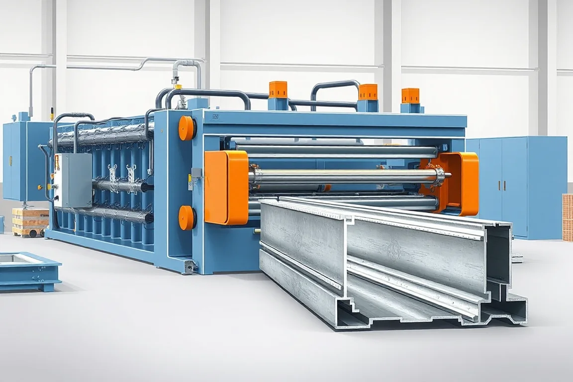
A window frame roll forming machine produces specified sheet-metal profiles used in a window or related glazed-frame construction. The exact component matters: an exposed steel frame, a glazing-retention profile and an internal reinforcement for another frame material have different functions and manufacturing requirements.
Begin with the complete window-system drawing and identify which profiles the equipment must make. Roll forming should be evaluated for those sections and their assembly interfaces, not treated as a universal substitute for extrusion, welded tube production or every other window manufacturing process.
Which window component is intended?
Separate the outer frame, opening sash, glazing beads, reinforcement and other accessories. A machine producing one of those profiles does not automatically manufacture the whole window. Their section shapes, lengths, features and end connections may differ substantially.
If the project concerns reinforcement inside a polymer frame, show the receiving cavity and fixing arrangement. If it concerns an exposed metal frame, include the glazing, seals, hardware and visible surfaces. The production brief should make that distinction explicit.
How should process suitability be assessed?
Review the longitudinal section, bend development, material and intended volume. Roll forming can be appropriate for repeated sheet-derived profiles, but complex cavities or other geometry may require a different construction or process. Tool access becomes important as returns close around the section.
Compare alternatives using the complete route, including holes, cut ends, corners, joining and finish. A process that makes the main section economically can still require substantial secondary work. Do not compare only the cost of a metre of unfinished profile.
A redesign from an extruded or other construction to a roll-formed profile needs product engineering review. Matching outside dimensions alone does not establish equivalent glazing, sealing or structural behavior.
What should the functional drawings show?
- Complete profile with bend radii and any joined seam.
- Glazing or receiving-cavity interfaces.
- Seal and gasket references where applicable.
- Hardware mounting faces and features.
- Drainage openings and other specified local details.
- Corner construction, material and final finish.
Provide mating components or controlled samples. Hidden clearances and contact surfaces are difficult to infer from a photograph of an installed window, yet they often determine whether the tooling produces a useful part.
How does the profile production route work?
The line presents the strip, creates required features, develops the section and produces the ordered lengths. Seam joining, thermal-separation construction, corner preparation or other operations belong in the route only where the selected product requires them.
- Release the correct component, material and feature schedule.
- Guide the strip with the required visible-face orientation.
- Produce included local features.
- Form the functional bends and returns progressively.
- Complete specified joining or end preparation.
- Inspect and identify the profile for window assembly.
Ask the supplier to identify the finished output clearly. A continuous profile, a cut member and an assembly-ready member are different deliverables with different equipment boundaries.
What matters about glazing and seal interfaces?
The relevant seating surfaces, bead contacts and seal locations must follow the window design. Inspect them as functional geometry rather than simply checking the outside profile envelope. Small return differences can affect assembly even when broad dimensions appear correct.
Use the intended mating components in controlled trials. Check engagement and alignment along representative lengths and at corners where required. Record unplanned force, trimming or local reshaping instead of accepting a modified sample as normal production fit.
Manufacturing compatibility is not the same as air, water, thermal or structural performance of a complete window. Those requirements need their applicable system design and verification beyond the forming-machine trial.
How should material and surface finish be specified?
List grade or alloy, thickness, strip width and finish for each component. Internal reinforcement and exposed frame profiles can have different surface and handling priorities. They should not inherit one generic material specification merely because they belong to the same window.
Inspect bends, joined areas, cut ends and visible faces using the actual production material. If finishing occurs after fabrication, define the final inspection condition and its relationship to seal or hardware fit.
Retain material identity with accepted samples. Later changes in section recovery, surface marks or mating fit should be investigated against both stock and setup rather than blamed automatically on one forming station.
How should drainage and hardware features be controlled?
Provide the exact feature schedule and finished datums. Drainage openings, fixing holes and hardware preparations serve different functions and can have different positional requirements. Do not add a generic repeated pattern without the product drawing.
Inspect the completed member after forming and end work. A feature correctly located on flat strip can still be wrong relative to the finished glazing or hardware interface. Check burrs and local distortion separately from position.
For handed or mirrored components, demonstrate correct orientation and identification. Similar profiles can be assembled incorrectly if their feature directions are not clear through collection and finishing.
Why do corner operations need separate attention?
The assembled frame depends on the way members meet at their ends. Specify mitres, notches, connectors, welding or another defined method. A straight cutoff does not automatically deliver corner-ready members for every window construction.
Assemble a representative frame or sash and measure its final dimensions, alignment and relevant interface continuity. Joining can introduce changes after the loose profile has passed inspection. Compare before-and-after measurements to distinguish those stages.
Where the project supplies only reinforcement or another internal component, use the intended receiving assembly instead of inventing an unrelated corner test. Acceptance should follow the actual component's function.
What profile flexibility should be reviewed?
Separate length and feature changes from new section geometry. A controller may handle one family of member lengths while another bead groove, return or cavity requires tools. Request a configuration matrix covering guides, rolls, feature dies and cutting parts.
Demonstrate commercially relevant transitions and a return to the original accepted setup. Include mating-component fit in the first-good-product assessment. A quick adjustment does not prove that the functional surfaces recovered correctly.
If several window components share a line, consider scheduling and storage. The factory needs the correct mix of frame, sash or reinforcement members, not simply the maximum length of whichever profile runs fastest.
How should handling preserve the product?
Protect visible surfaces and functional returns through cutoff, collection and packing. Define support for the length range and separate profiles that can scratch or deform each other when nested. Inspect normal packed output after movement.
Labels should identify component type, profile, material, length, feature schedule and order where needed. A reinforcement profile and an exposed frame member can have similar outlines while serving different assemblies, so clear references are important.
How should output and investment be compared?
Measure accepted components or matched assembly sets according to the project boundary. Include feature-making, end work, joining, inspection and packing. A steady forming speed does not describe the completed-window rate when other operations remain separate.
For planning only, a rectangular frame with two members of each length requires matched long and short parts plus its specified corner components. Producing extra long profiles does not complete missing short members. Use the actual bill of materials to balance the routes.
Compare quotations with the same component catalogue and final condition. Separate product development, qualification, finishing and purchased hardware from the forming equipment so responsibilities are clear.
What should acceptance demonstrate?
- Functional section dimensions in the approved material.
- Feature positions and correct component orientation.
- Length and end-preparation condition.
- Fit with glazing, seals, hardware or receiving cavities as applicable.
- Representative corner or receiving-assembly checks.
- Required product changes and setup recovery.
- Final surface condition, identification and packed output.
Retain matched reference components and setup records. They provide a repeatable baseline for the particular window profile rather than an ambiguous sample labeled only window frame.
Frequently asked questions
Does the machine make a complete window?
Not automatically. It makes the specified profiles and included operations. Glazing, seals, hardware, corners and other assembly work need their own scope or supply route.
Can any extruded window profile be roll formed?
No. The processes have different geometric possibilities. Review the section and product interfaces before adopting a formed construction. A redesign needs its own engineering assessment.
Is window reinforcement the same as the outer frame?
No. Reinforcement sits within another defined assembly, while an exposed frame has different interfaces and finish requirements. Identify the actual component before selecting tools.
Why test seals and glazing references?
They reveal whether functional returns and seating surfaces match the intended system. Overall width alone can miss an incompatible interface. The fit check complements, rather than replaces, complete-window performance verification.
Can drainage openings use a standard pattern?
Use the pattern required by the selected window design. Their location and function depend on that construction. Generic punching capability does not establish a correct drainage arrangement.
What should an enquiry include?
Provide component and assembly drawings, materials, finishes, local features, corner method and size family. Add mating references and the intended delivery boundary. This defines the complete profile-production requirement.

Continue your research
- Door & Window Profile Roll Forming Machines
- Steel Door Frame Roll Forming Machine
- Fire Door Frame Roll Forming Machine
- Hollow Metal Door Frame Roll Forming Machine
- Garage Door Track Roll Forming Machine
- Door Reinforcement Channel Roll Forming Machine
- How Door frame roll forming machine Works
- How To Choose a Door frame roll forming machine
- Door frame roll forming machine Price: What Affects the Cost?
Configuration & specification inputs
Match the configuration to your section drawing, material and production requirements.
| Parameter | Requirement / confirmation needed |
|---|---|
| Profile geometry | Specified window component with glazing, seal, hardware or receiving-cavity interfaces |
| Material | Component-specific grade/alloy, thickness and functional/visible finish |
| Thickness & grade | Review process feasibility for the actual section and material combination |
| Process route | Features, progressive section forming, required joining/end preparation and component inspection |
| Cutting | Coordinate end geometry with the selected corner or receiving assembly |
| Output | Accepted components or matched assembly sets with required secondary work included |
| Electrical supply | Confirm utilities for the selected forming, features, joining, end and handling scope |
| Acceptance | Measure functional returns, features and ends; test intended mating components and representative assembly |