
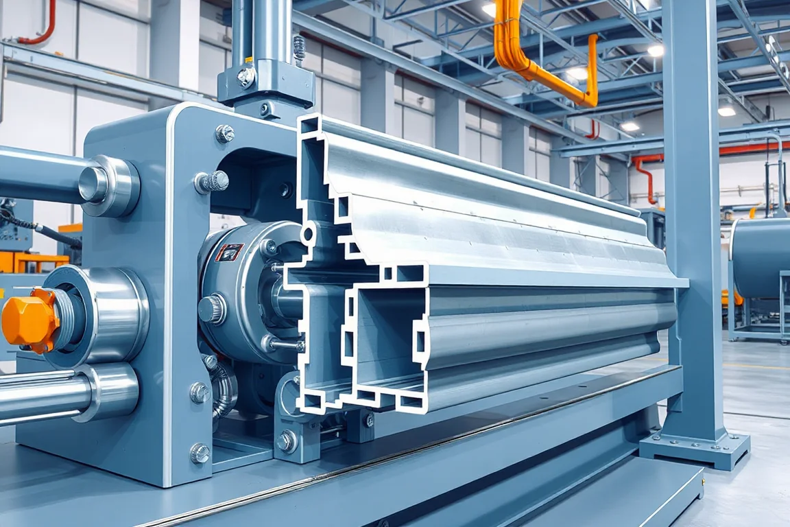
The roller and tooling design of a door frame roll forming machine is what translates flat sheet into a frame section whose rebate, jamb returns, hinge and latch features, and corner joining detail actually work in service. A roll count alone does not demonstrate quality. The useful question is how each bend develops, which surfaces locate the strip, how springback is managed, and how tooling changes when material or profile extremes change. This guide answers that question directly, then shows how to compare alternatives and interpret supplier quotes without treating unverified model ratings as specifications.
What door frame roll forming machine roller tooling design covers
Roller tooling design is the engineering of the forming stations, the strip support and guidance between them, and the auxiliary tools that punch, notch and cut the section. It also includes the tool identification and setup records that keep production repeatable. It is separate from the machine frame and drive specification, although the two must be matched. It is also separate from corner assembly, hardware fit, and any fire or security certification of a completed door system.
How the forming sequence and interfaces work
Production normally follows a sequence: blank or coil preparation, feature punching or notching, frame forming through a series of rolls, cutoff, and then corner assembly. Each stage has interfaces that must be defined before a tooling design can be assessed.
The first interface is strip condition. Coil feed, straightening and any pre-piercing affect how the strip enters the first forming station. If notching happens before forming, the notch geometry must survive the subsequent bends without distorting the features. If notching happens after forming, tool access to the finished section becomes the constraint. This choice is a design decision, not a default.
The second interface is the forming stations themselves. Door frame profiles typically combine a frame rebate, jamb returns and mounting flanges, so several bends may occur close together. Narrow returns and multiple bends require attention to tool access: the roll that forms one bend must not collide with the adjacent feature or with the strip edge. The designer must decide which surfaces locate the strip in each station, because the locating surface determines whether bends develop from a stable datum or from a moving edge.
The third interface is springback and material variation. Sheet steel springs back after bending, and the amount depends on grade, thickness and prior work. Tooling design addresses this through the intended bend allowance, overbend where appropriate, and consistent strip location rather than through a single fixed setting. Stainless or other alloys need separate tooling validation because their forming behavior and springback differ from the specified sheet steel.
The fourth interface is cutoff. The cutoff must be profile-supported so the end does not collapse or twist. The design should confirm cut lengths, end quality and any secondary operations such as hole burr control. Punch and cutoff tooling should be reviewed together with the roll tools, because a feature that is easy to form may be difficult to punch or cut in the same line.
Starting from functional geometry, not roll count
A frame profile must accept the door or glazing system, the hardware and the seals. That means the functional dimensions are the rebate depth and width, the seal land, the hinge and latch positions, and the corner joining detail. A section drawing and an assembly drawing should be available before selecting the manufacturing route. Without them, roll count is not a meaningful comparison.
The design should account for material variation and access to the final section. For example, a deep rebate with a short return can leave little room for a forming roll or for a punch to reach the hinge area. The designer may need to rearrange the bend order, add an idler, or move a feature to a secondary operation. These are engineering tradeoffs, not defects.
Assessing a tooling design proposal
When reviewing a proposal, ask how bends develop, which surfaces locate the strip, how springback is addressed, and how tooling is changed. A useful proposal identifies the forming stations, the locating strategy, the punch and cutoff arrangement, and the tool change method for the agreed material and profile extremes.
Check that the design references the actual profile, not a generic door frame. Check that it states the base-metal thickness and grade the buyer supplied, and that it treats any operating range as requiring supplier verification. Check that it keeps the accepted setup and tool identification together so production does not depend on an undocumented adjustment. A roll count without a forming design does not demonstrate quality.
Comparing production routes and tooling alternatives
There are several ways to produce a door frame section, and the choice affects tooling design. A dedicated roll forming line with integrated punching and cutoff suits a stable, high-volume profile. A line that forms a standard section and relies on secondary operations for hinge and latch features can reduce tooling complexity but adds handling and rework risk. A flexible line with quick-change tooling may suit multiple profiles but demands disciplined setup records.
For the forming stations themselves, alternatives include conventional sequence forming, where bends are developed progressively, and designs that use additional guidance or idlers to control narrow returns. The tradeoff is tool access versus strip stability. More guidance can improve repeatability but may restrict access for maintenance or tool changes. Fewer stations can reduce cost but may not develop the required geometry without distortion.
For cutoff, a profile-supported die is generally preferred over a simple shear, but the design must match the section and the end quality requirement. For notching, pre-forming versus post-forming is a decision that should be made with the punch and cutoff tooling in view, not in isolation.
How to read quotes and accepted-output cost
A quote for a door frame roll forming machine should be read by scope, not by headline number. The scope should state which profile and material the tooling is designed for, the base-metal thickness and grade, the punch and cutoff arrangement, the tool change method, and what acceptance testing is included. Installed power requires a confirmed equipment schedule; voltage, frequency and phase should be stated by the buyer.
Accepted-output cost is the cost per acceptable frame, not the cost per stroke. It includes scrap from setup, feature defects, end defects and corner rework. A line that produces fast but requires frequent adjustment may have a higher accepted-output cost than a slower line with stable tooling. Define accepted output per shift with the actual profile and material, and measure the finished frame after assembly as well as the unjoined section.
Acceptance checks for rebates, returns and corners
Inspect rebates and seal lands, then test actual hardware and a representative corner joint. Measure the finished frame after assembly as well as the unjoined section, because assembly can close or open the section. Verify tool changes using the agreed material and profile extremes. Keep the accepted setup and tool identification together.
A fire-door frame machine does not certify a fire-rated assembly. Rating depends on the complete tested and approved door system, including installation. The roll forming line produces a frame section; it does not by itself establish in-service performance.
Practical checklist for tooling design review
- Identify functional dimensions and mating parts, including rebate, seal land, hinge and latch positions.
- Request a section drawing and an assembly drawing before selecting the manufacturing route.
- Confirm whether notching happens before or after forming and how corners are prepared.
- Review punch and cutoff tooling together with the roll tools.
- Ask how bends develop, which surfaces locate the strip, and how springback is addressed.
- Check tool access to narrow returns and to the final section.
- Verify tool changes using the agreed material and profile extremes.
- Define accepted output per shift with the actual profile and material.
- Measure the finished frame after assembly as well as the unjoined section.
- Keep the accepted setup and tool identification together in production records.
Frequently asked questions
How many forming stations are needed for a door frame profile?
There is no universal number. The required stations depend on the bend count, the bend radii, the material and thickness, and how much guidance is needed for narrow returns. A design with fewer stations may not develop the geometry without distortion, while more stations can improve control but may restrict tool access. The right answer comes from the forming design, not from a roll count.
Should notching occur before or after forming?
Both are possible. Pre-forming notching can be easier to tool because the strip is flat, but the notch must survive subsequent bends without distortion. Post-forming notching avoids that risk but requires tool access to the formed section. The decision should be made with the punch and cutoff tooling in view, and it should be consistent with how corners are prepared.
How is springback handled in door frame roll tooling?
Springback is handled through the intended bend allowance, overbend where appropriate, and consistent strip location. The design should account for material variation rather than relying on a single fixed setting. Stainless or other alloys need separate tooling validation because their forming behavior differs from the specified sheet steel.
Can one tooling set run different door frame profiles?
It depends on how similar the profiles are and how the tooling is changed. A flexible line with quick-change tooling may suit multiple profiles, but it demands disciplined setup records and verification using the agreed material and profile extremes. A dedicated tooling set for one profile is simpler to control but less flexible. The tradeoff should be assessed against the actual product mix.
What should be measured on a finished frame after assembly?
Measure the functional interfaces: rebate depth and width, seal land position, hinge and latch positions, and the corner joint fit. Measure the finished frame after assembly as well as the unjoined section, because assembly can change the section. Test actual hardware and a representative corner joint rather than relying on a drawing check alone.
Does a roll forming line certify a fire-rated door frame?
No. A fire-door frame machine does not certify a fire-rated assembly. Rating depends on the complete tested and approved door system, including installation. The roll forming line produces the frame section; certification and in-service performance are separate matters.
Why component production is separate from assembly and certification
The roll forming line produces a continuous section and may punch, notch and cut features. Hinge preparation, latch features and corner assembly may be separate operations. The finished frame's performance depends on assembly, hardware fit and installation, not only on the formed section. Keeping these stages distinct helps avoid overclaiming what the tooling design can deliver.
Keeping production repeatable
Repeatability comes from documented setup and tool identification, not from undocumented adjustment. When a tool change is made, it should be verified using the agreed material and profile extremes. The accepted setup should be recorded with the tool identification so that production does not drift. This is a practical way to protect accepted output and reduce rework.
Continue your research
- Door & Window Profile Roll Forming Machines
- Steel Door Frame Roll Forming Machine
- Window Frame Roll Forming Machine
- Hollow Metal Door Frame Roll Forming Machine
- Garage Door Track Roll Forming Machine
- Door Reinforcement Channel Roll Forming Machine
- How Door frame roll forming machine Works
- How To Choose a Door frame roll forming machine
- Door frame roll forming machine Price: What Affects the Cost?