
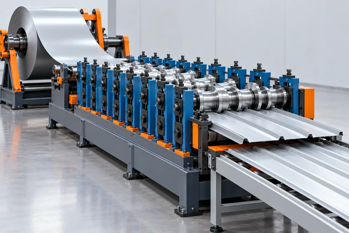
A wall cladding roll forming line makes the metal section that establishes a facade's face, joint and fixing edge. Its job is not simply to bend a strip into an attractive shape. The output must repeat the dimensions that allow adjacent panels and their attachment components to assemble while preserving the specified visible finish.
Define the facade component entering production
Single-skin siding, concealed-fix panels and insulated wall panels are different products. A former can produce a single-skin section or a metal facing that later enters a separate panel-making process. Identify which product leaves the proposed equipment before discussing its operation.
A wall section drawing should show the visible face, returns, joint and attachment. Add the adjacent panel and any clip or fastener interface. The production route follows these details; the word cladding alone does not specify whether a fixing flange is punched, a hook is formed or a core is bonded later.
Protect the correct coil face from the start
Loading and entry must present the chosen exterior face in the intended direction. Record finish orientation and any protective film with the coil specification. This is especially important when the back face looks similar during preparation but is not the surface intended for exposure.
The line layout should provide a controlled material path without leaving protective handling to improvisation. Include the incoming coil condition in the trial record. A defect already present on the coil requires a different response from one introduced at a forming contact or during stacking.
The face and edges develop as one section
Successive tools develop the section through intermediate shapes. The broad face connects two edges whose returns or fixing features may be unequal. Their relative position is important: producing two individually plausible edges does not ensure the assembled panel has the specified cover or reveal.
Where the drawing includes ribs, beads or other face features, treat them as part of the complete development. They affect appearance and geometry, not merely decoration. Any later change in face pattern should be reviewed for its interaction with the approved material and joint.
Hidden fixing geometry needs a mating check
A concealed joint may use a formed fixing flange, a separate clip or another defined arrangement. The roll former produces the relevant metal features, but the assembly depends on the selected mating components and installation sequence. Supply those components during development rather than choosing them after the tools are finished.
Use an assembly sample to inspect engagement, joint alignment and cover. Record any forcing or local modification needed to assemble it. A photograph of a completed joint can hide those difficulties, so the observed process is as important as the final appearance.
Feature operations must have a defined place
Some cladding products require holes, slots, notches or special ends. State their geometry and reference dimensions, then identify whether they are made inline or in a separate operation. A line making a constant transverse section does not automatically complete every end detail shown on an architectural drawing.
Separate continuous profile features from project-specific fabrication. For example, a repeated fixing feature and a unique opening around a facade penetration may need different production routes. Making that distinction prevents the line scope from expanding through assumptions during commissioning.
Cutting must preserve both the face and joint edges
Length cutting delivers the ordered panel but can also affect the ends of its functional returns. Inspect these areas after the actual cutting and discharge sequence. A central sample with perfect geometry does not demonstrate that both ends remain usable.
Define the finished length reference and any further fabrication allowance. If panels enter another process, the route should identify who controls the final dimension. Ambiguous ownership of a trim allowance can create a dispute even when the former repeats its programmed length correctly.
Discharge determines whether the facade finish survives
Completed panels need suitable support, separation and bundle identification. Appearance-sensitive faces should not be treated like bulk structural channels. Include the intended packing method in trials so the product is inspected after realistic handling rather than immediately at the roll exit only.
For mixed orders, keep finish, orientation and length information attached to the bundle. A panel delivered in the wrong finish batch can be unacceptable on a facade even if it is dimensionally correct. The production route should preserve product identity along with physical condition.
Inspect an assembly under agreed viewing conditions
A facade is seen across adjacent panels, not as one short loose coupon. Evaluate the assembled joint and visible face using agreed supports, lighting and viewing conditions. Distinguish dimensional nonconformity from appearance observations, then record both against the product specification.
This is a manufacturing and assembly review, not a substitute for the wall system's required project performance evidence. Weather resistance, fire behavior and structural design involve the complete specified assembly. A functioning roll former does not establish those outcomes by itself.
Trace one order through the complete route
For a practical process review, select one actual panel drawing and follow its information through coil selection, tooling setup, feature operations, cutting, inspection and packing. At each boundary, ask what identity and acceptance information travels with the material.
- Confirm the face, material and joint drawing before production.
- Approve the first panel and mating assembly.
- Check continued production and relevant end details.
- Inspect after discharge for handling marks.
- Identify the accepted bundle for the intended facade order.
Frequently asked questions about cladding production
Does a cladding former make complete insulated wall panels?
Not necessarily. It may make a metal facing only. Core preparation, bonding, pressing and finishing need their own defined equipment scope when the finished product is an insulated panel.
Can a vertical cladding profile be used horizontally?
The production geometry may be similar, but installation orientation can change joint and drainage requirements. Use the approved wall-system design rather than assuming that rotating a panel creates an equivalent application.
Are facade corners made by the same roll tools?
Only if they are explicitly included as supported profiles. Many corners and trims follow another forming or folding route. List them separately in the manufacturing plan.
Why is a long sample more informative than a small coupon?
It reveals handling, straightness, joint continuity and face appearance that a short section can miss. Use representative lengths and an assembly appropriate to the specified product, alongside detailed section measurements.
Continue your research
- Wall Cladding Roll Forming Machines
- Wall Panel Roll Forming Machine
- Metal Siding Roll Forming Machine
- Box Profile Wall Panel Roll Forming Machine
- Corrugated Wall Cladding Roll Forming Machine
- Trapezoidal Wall Cladding Roll Forming Machine
- How To Choose a Wall cladding roll forming machine
- Wall cladding roll forming machine Price: What Affects the Cost?
- Materials and Thickness for Wall cladding roll forming machine