
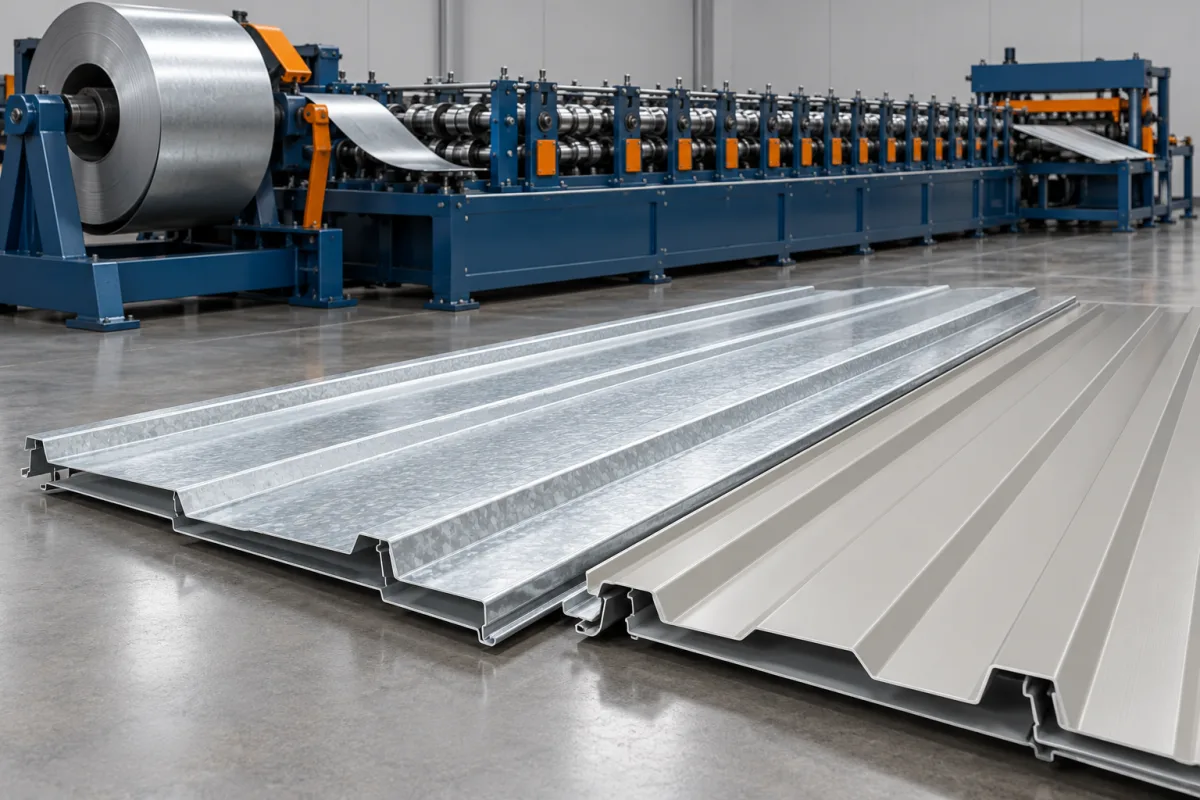
A wall panel roll forming machine makes repeatable metal cladding sections from coil, then cuts them into the lengths required for a building order. The finished product combines a visible face with ribs, laps or fixing edges that allow panels to form a continuous wall surface. Selecting the line begins with that installed panel, including how adjoining sheets connect and how the finished order will be handled.
The term wall panel covers several production routes. A single-skin metal sheet, a concealed-fix architectural profile and a bonded insulated panel are different products. This page focuses on forming the metal panel itself and explains which additional operations need to be identified before a machine configuration can be compared meaningfully.
What is included in a wall panel production line?
A typical project links coil payoff, strip guidance, progressive forming, length control, cutting and discharge. Depending on the product, the route can also include protective film, punching, another surface treatment or additional handling equipment. The useful question is not simply whether these functions appear in a brochure, but which are included for the actual drawing and material.
Define what leaves the line: a finished single-skin wall sheet, a facing awaiting lamination, or a profile needing further fabrication. This equipment boundary determines what the production business must supply elsewhere. A former that produces a metal facing does not by itself provide core preparation, bonding, pressing and curing for an insulated wall panel.
Which wall panel family should be specified?
Ribbed single-skin sheets
These profiles use repeated ribs and defined side laps to establish the finished section. The important drawing inputs include pitch, rib depth, pan shape and effective cover. Check the terminal ribs separately from the repeating center because they determine how adjacent sheets overlap.
Interlocking and concealed-fix profiles
The edge connection becomes a principal forming requirement. Specify the complementary returns and the clip or covered fixing flange used by the chosen design. This is more than a change in face appearance: the tooling must reproduce an installation interface that remains usable after cutting and handling.
Metal facings for insulated panels
The facing tools need to suit the intended core and panel joint. However, facing production is only part of the complete process. Keep core preparation, bonding and panel finishing in a separate equipment schedule so a single-skin former is not mistaken for a complete insulated-panel line.
What should the profile drawing show?
Describe the repeating cross-section, the two terminal edges and the installed relationship between panels. Overall width measures the physical sheet; effective cover describes the useful width after overlap or engagement. Those values should not be substituted for one another when ordering tools, planning coil usage or calculating the area supplied to a customer.
- Central geometry: rib spacing, rib depth, pan width and specified stiffening features.
- Edge geometry: lap direction, support returns, locks or fixing flanges.
- Assembly: adjoining panel position and the relevant fastener or clip interface.
- Material: grade, thickness convention, coating and visible-face orientation.
- Finished order: length range, end details, dimensional acceptance and packing requirements.
A profile nickname is useful for discussion but cannot replace this information. Two locally familiar panels may carry the same commercial label while differing at the lap or fixing detail. Use a controlled drawing and representative samples to resolve that difference before tool approval.
How does the strip become a finished wall sheet?
- Payoff: the coil is supported and presented to the line in the specified direction. Loading equipment and operator access must suit the coil envelope.
- Entry control: the strip is guided into the forming path. Any preparation or optional feature-making operation should have a defined place in the layout.
- Forming: successive roll stages develop the ribs, pans and terminal edges. The completed profile depends on the forming sequence as well as the final roll shape.
- Cutting: the required length is produced with suitable support for the formed section. Inspect the nearby ribs and laps as well as the cut edge.
- Discharge: finished sheets are supported, identified and packed without introducing unacceptable damage.
Ask the supplier to explain the actual proposed sequence, including whether cutting or feature operations occur before or after forming. The output and layout implications of that choice should be assessed against the intended panels rather than treated as a universal preference.
How should the material range be defined?
List material combinations, not isolated maximum values. Grade or alloy, base-metal thickness, strip width and surface condition belong together. The strongest material at the greatest width may place different demands on the line from a narrow, thinner product. A thickness range alone cannot describe the complete production envelope.
For coated products, identify the exposed side and finish requirements. Where a backing or underlayment is required, include it in the forming review and trials rather than assuming it can be added without affecting the process. The drawing, incoming material and intended surface layers should represent the saleable wall product.
Keep incoming-strip requirements separate from finished-sheet requirements. Coil condition and variation should be documented during trials so the source of a later dimensional or appearance problem can be investigated without guessing.
One profile, changeable tooling or a multi-profile arrangement?
A dedicated profile route is straightforward to evaluate when one section represents most orders. Its tooling and handling can be reviewed around a stable product. Length and color changes remain operational questions, but a new rib pattern or edge geometry may require additional tools.
A changeable arrangement serves a broader product range at the cost of more changeover work and setup control. Request a list of the guides, rolls, cutting components and other parts required for each variant. Time the change through to an accepted first sheet, not just the movement or removal of the main tooling.
A dual-level or second-path proposal should identify how coil feeding, drive, cutting and takeoff are shared. More than one forming path does not necessarily mean simultaneous production. Compare its scheduling value with the space and handling requirements of separate dedicated equipment.
What does the layout need beyond the forming stands?
Draw the complete movement of material: incoming coils, loading, strip entry, finished lengths, stacks and packed orders. Allow for the required equipment access and safe operating arrangements. A layout that fits the roll former but cannot discharge the longest intended sheet is not a complete production solution.
Pay particular attention to short and long products. Short sheets can require frequent handling, while long sheets need a supported path through inspection and packing. Define the stack and package format early enough to choose a suitable discharge arrangement. Protective separation may also be required for appearance-sensitive panels.
How can output be compared fairly?
Compare accepted wall panels over a defined trial order. State the lengths, material, profile, inspection requirements and included delays. Steady strip speed describes only part of the cycle; cutting, coil changes, profile changeovers and stack removal can determine how much usable material the route delivers.
For a clearly labeled planning example, 100 accepted panels that are each 3 metres long with a 1-metre effective cover represent 300 square metres of nominal panel coverage. That is arithmetic, not a machine capacity. It also does not deduct the project's openings, installation waste or other building-specific quantities. Keep production coverage and a building takeoff as separate calculations.
Report rejected starts and damaged sheets rather than counting all material that passed through the line as output. A faster trial is not necessarily a better result if it produces more panels that cannot be shipped.
What changes the equipment price and project scope?
The product family, material envelope, profile-change method and handling requirements establish the main comparison. Include all required roll tools, cutoff components, feature-making equipment, coil handling and discharge equipment. Identify site utilities, commissioning, training and inspection responsibilities separately.
Future variants deserve their own scope. Ask which dimensions can be adjusted, which changes need replacement tools and which products fall outside the proposed arrangement. This avoids comparing a basic single-profile former with a broader manufacturing package solely on their headline prices.
What should the production trial prove?
Use the approved section, actual material and representative lengths. Inspect sheets in the agreed support condition after normal discharge, then assemble several adjoining panels. The trial should connect dimensional measurements to the way the product is used.
- Confirm ribs, pans, terminal edges, finished length and effective cover.
- Check side-lap or joint engagement using the intended installation sequence.
- Inspect surface marking and the coating at bends and cut ends.
- Demonstrate the shortest and longest agreed trial products with suitable handling.
- Run a required changeover and verify the recovered first-good-sheet condition.
- Record accepted quantity, deviations and remaining scope items.
Keep the equipment trial distinct from structural and weather-performance assessment of the finished wall system. Manufacturing a drawing accurately and approving an entire building assembly are different responsibilities.
Frequently asked questions
Can a wall-panel machine also make roof panels?
Only where the required roof section is covered by the agreed tooling and equipment. Similar-looking ribs do not establish matching laps, material requirements or installation suitability. Supply both product drawings and compare the necessary change parts and production checks.
Does the line produce insulated panels?
A former may make a facing used in an insulated panel, but the complete product also requires its defined core and bonding process. Specify those additional operations explicitly. Do not treat the phrase wall-panel machine as confirmation of a complete lamination or reactive-foam line.
Should coil width equal installed panel width?
Not generally. Material is developed into ribs, returns and overlaps, while installed cover excludes the portion consumed by the joint. Obtain the input-strip requirement for the approved section rather than applying a fixed allowance to an arbitrary panel width.
Can a photograph replace a sample?
A photograph can communicate general appearance but usually omits hidden edges, bend radii and precise dimensions. Use a drawing and mating samples where available. They help establish whether a proposed profile will actually match the intended wall system.
Are trims included automatically?
No. Corners, flashings, openings and closures may require separate roll tools or folding equipment. Include an accessory list in the project brief so the production plan covers the finished order rather than only its main sheets.
What is the most useful starting information?
Provide the section drawing, material combinations, required lengths, installation references and typical order mix. Add finish and packing criteria. This gives equipment suppliers a common basis for comparing configuration, changeover and accepted output.
Choose the line around a complete wall product
A clear equipment brief connects the wall section, incoming coil, assembly method and finished order. Use that brief to compare complete routes and identify missing accessories or handling steps. The related siding and concealed-fix pages below explore narrower product choices when the wall-panel category needs to be developed into a specific manufacturing specification.

Continue your research
- Wall Cladding Roll Forming Machines
- Metal Siding Roll Forming Machine
- Concealed Fix Wall Panel Roll Forming Machine
- Box Profile Wall Panel Roll Forming Machine
- Corrugated Wall Cladding Roll Forming Machine
- Trapezoidal Wall Cladding Roll Forming Machine
- How Wall cladding roll forming machine Works
- How To Choose a Wall cladding roll forming machine
- Wall cladding roll forming machine Price: What Affects the Cost?
Configuration & specification inputs
Match the configuration to your section drawing, material and production requirements.
| Parameter | Requirement / confirmation needed |
|---|---|
| Profile geometry | Rib and pan geometry, terminal laps or locks, fixing details, overall width and effective cover. |
| Material | Specified coil grade or alloy, coating, visible face and any required backing or protective layer. |
| Thickness & grade | A reviewed matrix of thickness, strength, strip width and profile combinations. |
| Process route | Coil payoff, entry control, progressive forming, defined feature operations, length cutting and supported discharge. |
| Cutting | Agreed length range with acceptable cut ends and undamaged nearby ribs, laps or returns. |
| Output | Accepted panels and effective coverage for a stated order mix, with agreed delays and rejects recorded. |
| Electrical supply | Site supply and utilities matched to the complete forming and auxiliary-equipment schedule. |
| Acceptance | Section dimensions, assembled joint and coverage, finish, length, discharge and first-good-sheet changeover. |