
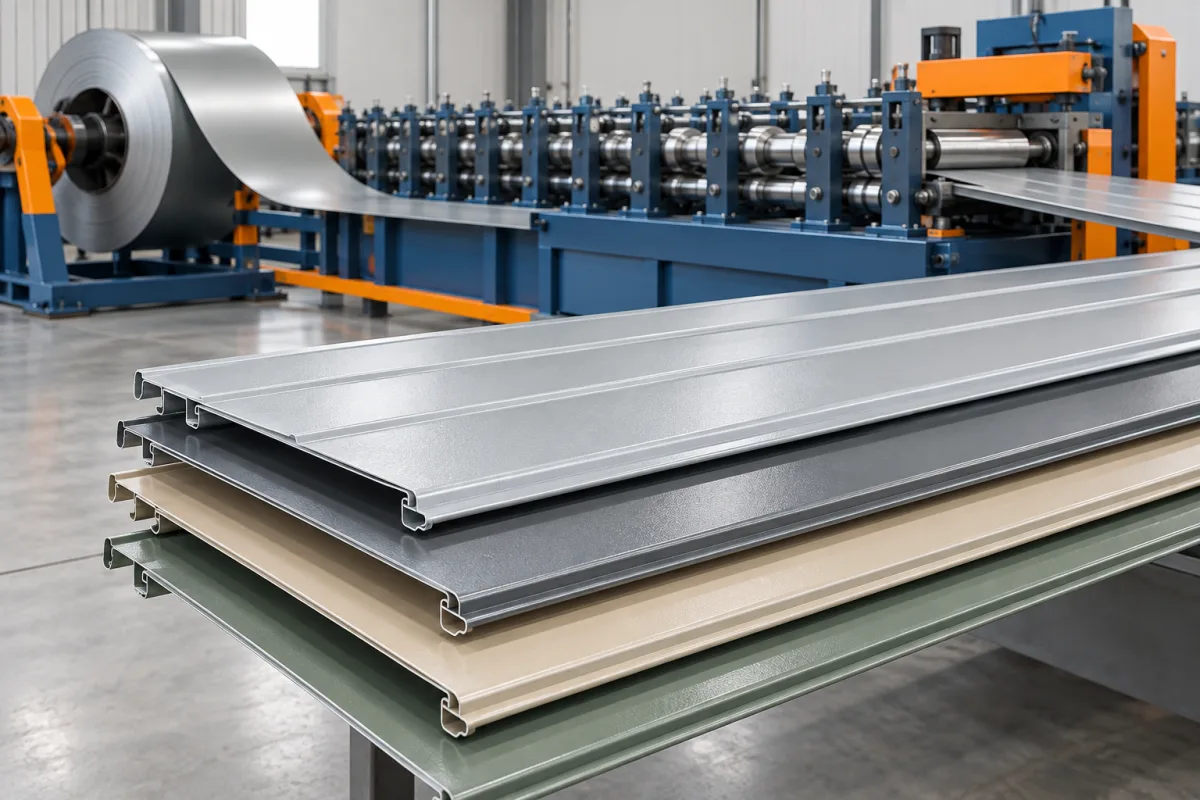
A metal siding roll forming machine converts coil into repeatable wall-cladding profiles, with the visible face, edge joint and fixing detail formed along the length of the panel. Its purpose is to make a siding product that assembles consistently across a facade, not simply to bend a strip into an attractive cross-section. The right configuration depends on the siding style, material, panel lengths and finish that the manufacturer intends to sell.
Siding can include ribbed wall sheets, interlocking strips and profiles with folded fixing edges. These products share an application but not necessarily a roll-tool design. Begin with the finished siding system and work backward to the forming line, its accessory equipment and its acceptance checks.
What does a metal siding roll forming machine produce?
The main output is a cut-to-length metal panel with a substantially constant cross-section. Successive rolls develop ribs, faces, returns and edge details from a flat strip. Depending on the selected profile, one edge may overlap another panel, engage a corresponding lock or provide a flange that will be covered during installation. These details determine how adjacent panels align and how much wall area each panel covers.
A siding line is therefore specified around a particular drawing or defined family of drawings. Cut length may change through the control system, while a different face pattern, rib spacing or edge lock can require different tools. A machine capable of producing one siding style should not be assumed to produce every other profile used on the same building.
Which siding style should the production line target?
Ribbed and lapped wall sheets
For this route, repeating ribs and terminal laps are central to the product. Specify effective cover, rib geometry and the edge that sits above or beneath the next sheet. Inspect several assembled panels, because a single section cannot demonstrate accumulated coverage or matching laps.
Interlocking siding strips
Here the connection between courses or adjoining strips becomes a principal tooling requirement. Define the engaging edges, visible face and fixing area together. If the chosen design needs slots or other fixing features, include their dimensions, pitch and production method in the equipment brief.
Architectural faces and decorative patterns
A broad flat face, shallow texture or board-like appearance introduces its own finish and geometry requirements. A printed coating, an embossed strip and a rib formed by the roll tools are different ways of creating an appearance. Identify which effect is required before asking whether it can be added to the line.
Where does roll-formed siding fit in a production business?
Repeated profiles supplied in varying lengths are a natural starting point for evaluating a siding line. A manufacturer serving standard wall systems may prioritize repeatability and straightforward coil changes. A business supplying many colors and small project batches may care more about setup recovery, surface protection, identification and packing.
List a representative week's orders rather than selecting equipment from a maximum-speed figure. Include color changes, short and long panels, the required profile variants and matching trims. If most work consists of constantly changing folded shapes in very small quantities, compare a flexible folding route with dedicated roll tooling before committing to the production layout.
How does the siding production process work?
- Coil loading and payoff: support the specified coil and feed the strip in the correct orientation. The layout must accommodate safe loading and protect the face intended to remain visible.
- Entry preparation: guide the strip into the forming path. Any required straightening, film application or feature-making operation should appear explicitly on the line layout.
- Progressive forming: develop the central profile and edge details through successive stages. Returns and locks need a sequence that permits tool access while maintaining the required face geometry.
- Length control and cutting: cut the requested panels using an arrangement suited to the section. Check both the cut edge and the nearby lock, flange or rib for distortion.
- Discharge and packing: support the finished panel, separate appearance-sensitive surfaces and identify the order. Damage introduced during unloading still makes the panel unacceptable to the customer.
The exact order of punching, forming and cutting depends on the proposed design. Ask which features are completed in-line and which require a separate operation. This makes it possible to compare complete production routes rather than two machines with different exclusions.
Which dimensions and material details define the configuration?
A useful specification distinguishes the visible face from the joining and fixing geometry. For example, overall panel width is not necessarily the installed cover width: part of the sheet may disappear into an overlap or lock. Similarly, the height of an edge return says little about whether its mating surface engages correctly.
- Profile drawing: face width, ribs, returns, bend radii, lock geometry and fixing-flange details.
- Coverage: effective cover and the installation sequence used to measure it.
- Input material: steel grade or aluminum alloy, thickness convention, strip width and coating.
- Surface requirements: visible side, protective film where specified and acceptable contact marking.
- Length schedule: shortest, longest and commonly ordered lengths, including end-feature requirements.
- Assembly references: matching panels, fixings, clips if applicable, trims and closures.
Provide these as a linked product brief. Separate maximum width and thickness figures do not establish that every combination can run with every material or profile.
Dedicated tooling, changeable tooling or another forming path?
A dedicated profile arrangement concentrates the equipment around one established product. It is worth considering when the same section dominates production and the main changes are color or length. Its limitation is that a substantially different cross-section may require another tooling solution.
Changeable tooling can support a broader range, but the useful comparison is the complete changeover. Include the guides, rolls or cassettes, feature tools, cutoff support, programs and first-piece inspection. A proposal should identify which components are shared and which are specific to each siding profile.
A second forming path is another possible arrangement for distinct products. Review floor space, coil feeding and takeoff rather than assuming two paths mean simultaneous production. Use the expected order mix to decide whether the extra equipment solves a real scheduling problem.
How should the painted or finished face be protected?
Appearance depends on more than the last roll stand. Trace the visible face from coil loading through entry guides, forming contacts, cutoff supports and stacking. A trapped chip on a downstream support can mark a panel that left the rolls in good condition. Handling and packing requirements should therefore be part of the original equipment discussion.
Use the intended production material in trials. Equal nominal thickness does not make coated steel and aluminum behave identically, and a result obtained on an unfinished strip does not demonstrate the appearance of the specified painted product. Agree the viewing conditions and reference sample for finish inspection so the acceptance decision is repeatable.
What determines usable siding output and project cost?
Usable output is the number of acceptable panels delivered from the complete route. Frequent color changes, short lengths, punching cycles or careful separated stacking can matter more than the maximum strip speed. Record accepted quantity, elapsed time and rejected starts during a representative order, with a clear statement of which delays are included.
For coverage planning, multiply accepted panel length by effective cover width. Use consistent units and exclude rejected pieces. This distinguishes saleable wall coverage from the length of material that merely passed through the machine.
Cost comparisons should include coil handling, all required profile tools, feature-making equipment, cutting, discharge, protective packing provisions and commissioning responsibilities. A machine-only offer can appear inexpensive while leaving essential operations outside the package. Additional profiles and future geometry changes should be priced separately from routine length changes.
What should a siding acceptance trial demonstrate?
Start with an approved drawing, representative material and a written order schedule. Retain samples from the beginning and later portions of the run. Inspect the product after normal cutting and handling, not only while the strip is supported inside the machine.
- Measure the section, effective cover, relevant fixing features and finished length.
- Assemble several panels in the intended sequence, checking engagement and alignment.
- Inspect cut ends and locks for deformation that affects installation.
- Review face appearance and coating condition against the agreed reference.
- Demonstrate an agreed length, material or profile change and inspect the first accepted output.
- Check stacking, separation and identification of the resulting order.
This trial addresses manufacturing acceptance. The facade's structural, weathering and installation requirements still belong to the specified wall system and its project design.
Frequently asked questions
Can the same line make steel and aluminum siding?
It depends on the specified materials, profiles and verified equipment configuration. Review alloy or grade, thickness, coating, bend details and springback with the supplier. Request representative trials rather than treating the material change as a simple switch of coil.
Does a different panel length require new rolls?
Changing length is different from changing cross-section. A line with suitable controls and cutting arrangements can be configured for different lengths within its agreed operating range. The supporting and packing arrangements also need to suit those lengths.
Will the siding line make corners, starter strips and window trims?
Only where those profiles and operations are expressly included. Accessories may use separate roll tools, folding or other fabrication. Prepare a trim list alongside the main siding drawing so the equipment plan covers the products needed to complete an order.
Can existing siding be matched from a photograph?
A photograph helps identify the style but rarely defines hidden locks, bend radii or exact coverage. Supply a measured drawing and representative mating samples. Matching an installed system requires attention to both the visible face and the concealed interfaces.
Is embossing part of every siding former?
No. Embossing, printed finishes and roll-formed ribs are separate specification choices. State the intended texture and whether it is present on the incoming coil or must be produced by additional equipment. Then evaluate its effect on forming and surface acceptance.
What should be prepared before requesting a configuration?
Bring the section drawing, material schedule, length mix, intended finish and assembly references. Add the expected batch pattern and accessory list. Together these inputs allow a meaningful discussion of tools, handling, changeover and accepted output.
Build a complete siding production brief
Start with the panel customers will install, then connect every edge, surface and accessory requirement to a production operation. This keeps the equipment comparison focused on a saleable siding system. Explore the related wall-panel profiles below when deciding whether a lapped sheet, interlocking siding strip or concealed-fix panel best matches the intended product range.

Continue your research
- Wall Cladding Roll Forming Machines
- Wall Panel Roll Forming Machine
- Concealed Fix Wall Panel Roll Forming Machine
- Box Profile Wall Panel Roll Forming Machine
- Corrugated Wall Cladding Roll Forming Machine
- Trapezoidal Wall Cladding Roll Forming Machine
- How Wall cladding roll forming machine Works
- How To Choose a Wall cladding roll forming machine
- Wall cladding roll forming machine Price: What Affects the Cost?
Configuration & specification inputs
Match the configuration to your section drawing, material and production requirements.
| Parameter | Requirement / confirmation needed |
|---|---|
| Profile geometry | Visible face, ribs, effective cover, mating lock or lap, fixing flange and bend radii for the selected siding system. |
| Material | Specified coated steel or aluminum; identify grade or alloy, visible face, coating and protective film where required. |
| Thickness & grade | Define base-metal thickness and the material combinations required for each siding profile. |
| Process route | Coil payoff, entry preparation, specified feature operations, progressive forming, length cutting and protected discharge. |
| Cutting | Finished-length range, supported cutoff and acceptable edge, rib and lock condition after cutting. |
| Output | Accepted panels or effective wall coverage over a stated trial, including the agreed changeovers and handling. |
| Electrical supply | Site voltage, frequency and phase, paired with the final equipment and auxiliary-utility schedule. |
| Acceptance | Profile dimensions, assembled coverage and engagement, finished length, visible finish and handling condition. |