
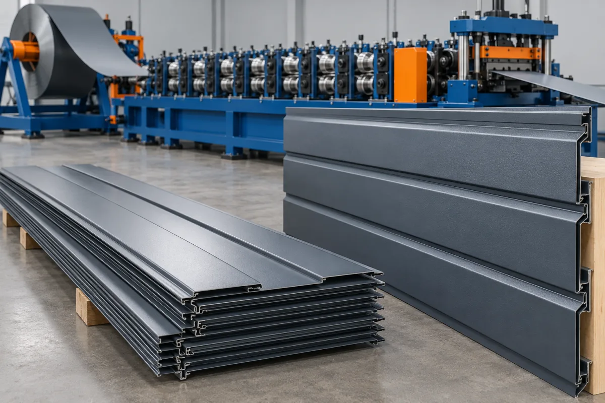
A horizontal metal siding roll forming machine produces profiles intended to form courses across a wall. The visible face may resemble lap siding, a flat architectural strip or another approved cladding pattern. What matters to the machine specification is the complete upper and lower edge relationship, including the attachment detail hidden after the next course is installed.
Horizontal siding is not defined merely by rotating a vertical panel. Course overlap, joint engagement, end treatment and opening interfaces need to follow the chosen wall-system design. The production route should be developed around those details rather than a general siding photograph.
Which horizontal siding family is required?
Identify whether the product uses a lapped face, an interlocking return or another course joint. Define the visible height contributed by each piece after installation, not only its physical width. Raised features and shadow lines should be shown with their actual cross-section.
Separate the main siding from starter strips, corners and termination trims. These accessories can control fit but may need different fabrication equipment. A complete product range is broader than the main longitudinal profile.
How should the course joint be described?
Show two adjoining courses in section. Identify the engagement surfaces, overlap, fixing flange or clip, and any clearance required by the design. If holes or slots are specified, show their position relative to the formed edge and finished ends.
The drawing should explain installation sequence as well as final appearance. A hidden fixing that cannot be accessed during assembly is not resolved by making the visible face accurate. Include production-intent attachment components in the tooling review.
What dimensions affect facade alignment?
Effective course height, reveal and end squareness influence the repeated appearance across a wall. The inspection plan should measure these consistently and check several joined pieces. Small recurring differences can become apparent over multiple courses even when one piece looks acceptable.
- Define physical width and installed course contribution separately.
- Mark the datum for upper and lower return measurements.
- Specify visible-face geometry and any embossed features.
- Show starter, corner and opening interfaces.
- State required end joints or length allowances.
Do not derive these dimensions from a rendering alone. An approved cross-section and assembly sample provide a much more reliable tooling target.
How does the line make the siding?
Controlled coil entry presents the strip to any preparation or feature-making operations. Progressive rolls develop the face and course-lock edges. Length control and the selected cutoff then produce the required pieces, followed by supported takeoff and order sorting.
Ask how fixing features are registered to cut ends and whether special notches are included. Their location can matter at corners and end joints. A basic roll former without the relevant tools should not be assumed to complete those secondary details.
How should coating and visible-face quality be handled?
List material grade or alloy, base-metal thickness and finish. Identify the visible face and any film or textured surface. The actual material should be used for trials because forming behavior and appearance can change between combinations.
Inspect the broad face and tight returns separately. A satisfactory face does not establish a usable lock, while a functional lock does not excuse coating damage. Repeat both checks after normal handling to identify marks or deformation introduced by stacking.
Can course height or face style be changed?
Some designs may support adjustments within a defined family, while others require different rolls or cutoff parts. Changing the face width is not necessarily equivalent to changing the upper and lower joint geometry. Request a matrix showing the exact supported variants.
For each transition, demonstrate the first accepted assembly after changeover. Include feature tools, guides, cutoff support and inspection in the timing. This reveals the real scheduling effect of offering multiple siding styles from one line.
How should end joints and accessories be included?
Show the intended end-joint method and any preparation required on the siding. It may involve separate trims, specified overlaps or other system details. The line scope should identify what it completes and what remains a downstream operation.
Use starter and termination references during acceptance. A machine can produce consistent siding that still does not fit the chosen accessory if the interface was never agreed. Check the first and last courses as well as the repeating middle joint.
What proves useful output for horizontal orders?
Evaluate accepted pieces from a realistic cut list, including package sorting and any special ends. Long identical pieces do not represent every facade order. Short lengths around windows and returns can change the influence of cutting and handling on output.
- Verify section and feature dimensions.
- Check course engagement with intended attachments.
- Assemble multiple courses and inspect alignment.
- Fit starter, end and termination references.
- Inspect finish after ordinary packaging.
- Record accepted quantity and rejected-piece causes.
Use this result to compare complete routes. A nominal forming speed is useful context, but it is not a substitute for the number of correct siding pieces ready for delivery.
Frequently asked questions
Can one siding profile be used in both directions?
Only where the selected wall-system design supports both orientations. Review the joint, supports and terminations rather than assuming that a rotated section performs the same function.
Are starter strips made on the main machine?
They require their own tooling or fabrication route unless explicitly included. List all accessory sections so the purchase covers the intended siding package without hidden production gaps.
Can the fixing flange be changed independently?
That depends on the forming and feature-making design. A flange change may affect engagement, access and cutoff support. Ask for an engineering review of the complete joint.
Why check several courses at once?
The assembly reveals repeated reveal and alignment behavior that a single cross-section cannot show. It also tests whether the intended installation sequence works with actual production pieces.
What should a buyer provide first?
Provide the section and course assembly, accessory references, material matrix, length schedule and required features. Add the order mix and packaging plan to make output discussions realistic.
Specify the course, not just the face
A strong horizontal-siding brief connects appearance to the upper and lower joints, attachments and accessory system. That gives tooling design and acceptance a clear target and supports repeatable production of usable facade components.

Continue your research
- Wall Cladding Roll Forming Machines
- Wall Panel Roll Forming Machine
- Metal Siding Roll Forming Machine
- Box Profile Wall Panel Roll Forming Machine
- Corrugated Wall Cladding Roll Forming Machine
- Trapezoidal Wall Cladding Roll Forming Machine
- How Wall cladding roll forming machine Works
- How To Choose a Wall cladding roll forming machine
- Wall cladding roll forming machine Price: What Affects the Cost?
Configuration & specification inputs
Match the configuration to your section drawing, material and production requirements.
| Parameter | Requirement / confirmation needed |
|---|---|
| Profile geometry | Horizontal course face with defined upper and lower joint, installed contribution and fixing arrangement. |
| Material | Specified coated metal with visible-face and protective-layer requirements. |
| Thickness & grade | Grade and base-metal thickness combinations assessed through course-lock forming and engagement. |
| Process route | Coil preparation, registered features, face and course-edge forming, cutting and order sorting. |
| Cutting | Specified siding lengths and end-joint preparation with intact course returns. |
| Output | Accepted horizontal siding orders including special ends, assembly checks and package sorting. |
| Electrical supply | Site supply and auxiliary equipment requirements for the complete siding process. |
| Acceptance | Course fit and alignment, starter and termination interfaces, feature positions and finish after handling. |