
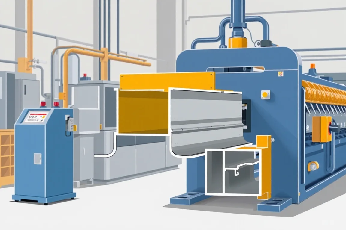
What an elevator profile roll forming machine actually produces
The phrase covers equipment that forms a strip of metal into a continuous constant cross-section used in or around elevator systems. The formed part is not the elevator. It is a component: a guide rail, door track, sill support, enclosure trim, bracket or structural stiffener. Different elevator profiles have different functions, and those functions change what the roll forming line must do.
A guide rail presents running surfaces that lift car guide shoes or rollers. A door track presents a path for door hangers. An enclosure profile may be mostly cosmetic or may include mating flanges for panels. A structural stiffener may need specific bend radii and web depths to carry load. Because these roles differ, a machine described only as an elevator profile roll forming machine is not evidence that it can produce a particular part to the required function.
The output is a constant cross-section, cut to length. Whether that is the right production route depends on the drawing, the material, the thickness and the production volume. The section below separates the machine, the tooling, the secondary operations and the acceptance process so that each can be evaluated on its own terms.
Reading the part drawing as a manufacturing input
Before any roll forming decision, the part drawing must be complete enough to describe the full cross-section: all bends, flanges, returns, embosses, holes, notches, cutouts and mating interfaces. Functional datums should be identified, not just nominal dimensions. A datum is the surface or feature from which other dimensions are measured and inspected. If the drawing does not state which features are functional, the production team may choose a different measurement basis than the design team intended.
Bend development matters. Each bend has an inside radius, an angle and a direction. The strip must be long enough to feed through the forming stations, and the bend sequence must allow the material to deform without tearing or wrinkling. Enclosed or re-entrant features, such as a hem or a return flange, restrict tool access. They may require special roll arrangements or a different process route. Holes and notches that fall on a bend or near a bend can distort during forming. Their position relative to the bend line is a drawing detail that affects tooling and inspection.
Incoming strip variation also matters. Thickness tolerance, yield strength range, surface finish and coil set can change the formed shape. A drawing that specifies only nominal thickness and grade leaves the forming window undefined. The buyer should state base-metal thickness and grade, and confirm with the supplier what operating range is practical. That range is not a machine rating to be assumed; it should be established for the actual material and profile.
Material and thickness: the limits of a feasibility review
Mild steel, stainless steel, aluminum and other nonferrous strip behave differently in roll forming. Stainless steel tends to work-harden and may need more forming stations or gentler bend increments. Aluminum can gall or mark unless roll surfaces and lubrication are considered. Higher-strength steel springs back more, so the roll designer must compensate for elastic recovery. These are general tendencies, not fixed rules, and they must be evaluated for the specific grade and thickness.
A feasibility review usually starts with the strip material and thickness, the cross-section, the bend radii and the required tolerances. The reviewer looks at whether the section can be formed progressively without excessive strain, whether the rolls can reach the functional surfaces, and whether the cutoff can support the profile while cutting. If the section is too complex for a single roll forming line, the route may combine roll forming with press braking, stamping or secondary machining.
The thickness field is a selection requirement, not a machine specification. The buyer states the base-metal thickness and grade. The supplier verifies whether the proposed line can run that range with acceptable quality. A machine that forms one thickness well may not form a significantly different thickness without tooling changes or process adjustment. That is why a feasibility review should use the intended production material, not a substitute that is easier to form.
Production route: from coil to finished part
The typical route is feasibility review, coil preparation, progressive forming, secondary features and cutoff. Each step has a different purpose and a different acceptance boundary.
Coil preparation includes loading, uncoiling, straightening and feeding. Poor straightening can leave residual curvature that shows up as a bowed or twisted finished part, even if the cross-section dimensions look correct. The feed system must handle the coil width and thickness without marking the surface. Coil joins or surface defects should be managed so they do not damage rolls or produce out-of-tolerance sections.
Progressive forming uses a series of roll stations. Each station bends the strip a small amount until the final section is reached. The number of stations depends on the section complexity and material. More stations can allow gentler bends and better control, but they also add length, cost and setup complexity. Fewer stations can be sufficient for simple profiles. The roll designer decides the sequence; the buyer should ask how each bend develops and whether any feature restricts roll access.
Secondary features include punching, notching, embossing, lancing or drilling. These operations can be integrated into the line or performed offline. Integrated punching is efficient for high volumes, but it requires dedicated dies and may limit flexibility. Offline operations can be more practical for low volumes or for features that are difficult to place in the forming sequence. Holes that are punched before forming may distort; holes punched after forming may require access that the profile does not allow. The choice affects tooling cost and part quality.
Cutoff is the final forming operation. The cutoff tool must support the profile while cutting so that the section does not collapse or distort. Cut length accuracy, end squareness and burr condition are common requirements. Some profiles need secondary operations after cutoff, such as deburring, tapping or bending. Those operations should be listed in the equipment scope so that the production line is not expected to deliver a finished part it cannot produce.
Comparing production alternatives
Roll forming is not the only route for elevator profiles. Press braking forms a flat blank in a brake press, one bend at a time. It is flexible and has lower tooling cost for small quantities, but it is slower for long runs and can produce more dimensional variation from handling. Stamping can produce complex features in a single stroke, but the tooling is expensive and the part size is limited by press capacity. Extrusion can produce constant cross-sections in aluminum or other nonferrous metals, but it requires a different material and may not match the strength or surface requirements of steel profiles. Welded fabrication can combine several pieces into a larger assembly, but it adds welding distortion, inspection and labor.
The choice depends on geometry, material, volume and functional requirements. A constant cross-section with suitable bend development and a steady production volume favors roll forming. A complex shape with undercuts or varying cross-sections may favor stamping or fabrication. A small batch of a simple profile may favor press braking. A nonferrous profile with a constant section may favor extrusion. The comparison should include not only the forming step but also secondary operations, inspection and the cost of future changes.
Tooling scope and future product changes
Roll forming tooling is specific to a profile and material. A set of rolls for one elevator guide rail will not produce a door track without changes. Quotations should separate engineering, roll tools, punch dies, cutoff tools and any provisions for future size changes. The cheapest initial arrangement may make later product changes expensive if the line lacks interchangeable tooling or if the control system cannot store additional recipes.
Changeover frequency and batch size should be part of the decision. A dedicated line with high steady-state speed is less useful for small, varied batches if changeover takes a long time and generates scrap. A line with quick-change tooling may have a lower peak speed but higher effective output for mixed production. The buyer should define the production target per shift with the actual profile and material, not an idealized rate.
Power, controls and facility interfaces
The electrical supply is a facility interface. The buyer should state voltage, frequency and phase. Installed power requires a confirmed equipment schedule that lists motors, drives, heaters and controls. That schedule is part of the supplier's proposal, not a value to be assumed from a generic machine description. The control system should be able to store and recall forming parameters for each profile. It should also provide diagnostics that help operators identify feed, forming or cutoff issues without adjusting moving machinery.
Safety systems, guarding and emergency stops are part of the line. They should be reviewed with the responsible engineer. The buyer should confirm that the proposed arrangement meets the applicable site and regulatory requirements for the installation. This article does not provide operating instructions for moving machinery.
Acceptance: inspect functional datums, not every dimension
Acceptance should prioritize functional datums and mating features. Tolerancing every dimension equally can increase cost without improving performance. The inspection plan should define which surfaces guide, which surfaces mate and which dimensions affect assembly or downstream processing. The section should be inspected in a defined free or restrained state, and the measurement method should be documented. A profile measured in a free state may differ from the same profile clamped in a fixture, and both may be valid for different purposes.
First-off pieces and a representative steady-production sample should be checked with agreed gauges. The sample should be produced from the agreed material and profile, not an easier demonstration substitute. The acceptance record should note the measurement method, the fixture state and any deviations. If the part is used in an elevator system, the applicable approval requirements are separate from the forming process. Elevator safety and system certification depend on the complete assembly and its installation, not only on the cross-section dimensions.
Checklist for specifying and reviewing a production line
- Complete cross-section drawing with functional datums, bends, holes and mating interfaces.
- Specified strip material, base-metal thickness and grade.
- Feasibility review using the intended production material and profile.
- Process route that states coil preparation, progressive forming, secondary features and cutoff.
- Cutoff requirements: profile support, cut lengths, end quality and secondary operations.
- Production target per shift with the actual profile and material.
- Electrical supply voltage, frequency and phase.
- Tooling scope: engineering, roll tools, punch dies, cutoff tools and future size changes.
- Changeover frequency, batch size and setup scrap.
- Acceptance checks for functional datums, mating features and measurement method.
- Clear separation between component forming and elevator system certification.
FAQ: practical questions about elevator profile roll forming
Can any elevator profile be roll formed?
No. Roll forming suits constant cross-sections with suitable bend development and production volume. Profiles with undercuts, varying cross-sections or very small quantities may be better produced by press braking, stamping, extrusion or welded fabrication. A feasibility review should confirm the route for the actual part.
What information is needed to quote a machine?
The supplier needs the complete cross-section, material, base-metal thickness and grade, hole and notch details, functional datums, cut length and end requirements, production target and electrical supply. Missing information leads to assumptions that may not match the part.
How should the cutoff be specified?
Specify how the profile is supported during cutting, the required cut length tolerance, end squareness and burr condition. If deburring, tapping or bending is needed after cutoff, list it in the equipment scope so it is not treated as an unplanned operation.
What does an elevator profile roll forming machine manufacturer need to provide?
A manufacturer should provide a clear equipment scope, tooling list, feasibility review, acceptance plan and documentation for the control system and safety devices. The buyer should compare that scope with all secondary operations needed for a finished part.
Is a machine claim the same as elevator component compliance?
No. A machine that forms a profile to nominal dimensions does not by itself demonstrate compliance with elevator safety or system certification. Those requirements apply to the complete component or assembly and should be reviewed with the responsible engineer.
How can a buyer assess the production line?
Run the agreed material and profile, inspect first-off pieces and a representative steady-production sample with the agreed gauges, record changeover steps and setup scrap, and compare the written equipment scope with the finished part requirements. This gives a practical basis for acceptance.

Continue your research
- Custom & Industrial Profile Roll Forming Machines
- Custom Profile Roll Forming Machine
- Hat Channel Roll Forming Machine
- C Channel Production Line
- Z Channel Production Line
- Electrical Cabinet Frame Roll Forming Machine
- How Custom profile roll forming machine Works
- How To Choose a Custom profile roll forming machine
- Custom profile roll forming machine Price: What Affects the Cost?
Configuration & specification inputs
Match the configuration to your section drawing, material and production requirements.
| Parameter | Requirement / confirmation needed |
|---|---|
| Profile geometry | Elevator profiles can have distinct guide, enclosure or structural roles. Establish the actual part and applicable approval requirements; a generic profile machine claim is not evidence of elevator-component compliance. |
| Material | Specified steel, stainless steel or nonferrous strip after feasibility review |
| Thickness & grade | Buyer to specify base-metal thickness and grade; operating range requires supplier verification. |
| Process route | Feasibility review → coil preparation → progressive forming → secondary features → cutoff |
| Cutting | Confirm profile-supported cutoff, cut lengths, end quality and any secondary operations. |
| Output | Define accepted output per shift with the actual profile and material. |
| Electrical supply | Buyer to state voltage / frequency / phase. Installed power requires a confirmed equipment schedule. |
| Acceptance | Define functional surfaces, joining and downstream processing for the selected part. Review inspection with the responsible engineer. Elevator safety and system certification are separate from forming a section to its nominal dimensions. |