
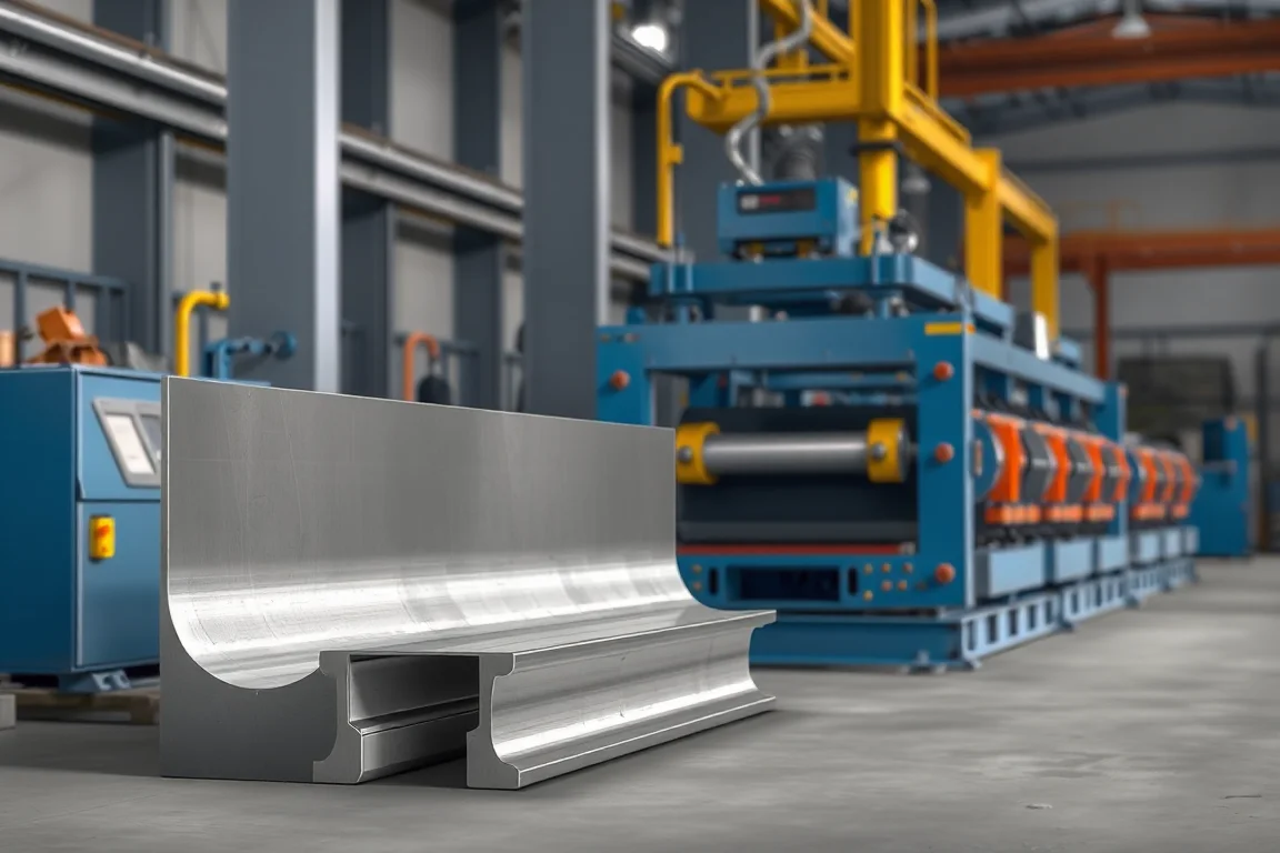
What the finished hat channel actually is
A hat channel is a constant-cross-section profile with a raised central web and two outward mounting flanges. In its simplest form, it looks like a top hat: the web forms the crown, two side walls drop from the web, and the flanges project horizontally outward at the bottom. The section is closed only by geometry, not by a seam. The exact shape is defined by the complete cross-section drawing, not by a generic name. Two hat channels with the same web width can differ in flange width, side-wall angle, corner radii, hole pattern and material thickness, and those differences change how the section locates and fastens in the final assembly.
The functional datums are the surfaces that position the channel or carry load. Usually the outward flange contact surfaces and the raised web top are the critical interfaces. Corner radii between the web and side walls, and between the side walls and flanges, affect stiffness, coating performance and how tightly the channel nests with other parts. A sharp internal radius may be desirable for a tight fit, but it also concentrates strain during forming. The drawing should define each radius and state which dimensions are functional datums and which are reference. That distinction guides tool design and inspection.
Mating interfaces and features that drive tooling
The mating interfaces determine whether a simple roll forming line is sufficient or whether progressive tooling with secondary operations is needed. Flange contact surfaces may need to be flat and parallel within a defined tolerance so that the channel sits without rocking. Web holes may serve as bolt or screw locations; their position relative to the flange edges matters more than their absolute location if the flange edges are the assembly datum. Slots, notches, embosses, lance tabs and edge cutouts are common secondary features. Each one adds a station or a separate operation, and each one can introduce distortion if it removes material or creates an unbalanced section.
Re-entrant features, such as a hem or a return lip on the flange, restrict tool access. A roll forming line can sometimes produce them with special side rolls or a dedicated pass, but the feasibility review should confirm that the rolls can reach the feature without interfering with the rest of the section. Enclosed features that wrap back on themselves are usually formed in stages, and the strip must be supported to avoid buckling. The drawing should show the forming direction and any pre-pierced holes, because hole distortion near a bend is a common source of rejected parts.
Material and strip inputs
The material grade, temper, coating and thickness range all influence formability. Mild steel, high-strength low-alloy steel, stainless steel and nonferrous strip behave differently in the same tooling. Higher strength and lower elongation increase springback and the risk of edge cracking, so the bend radii and the number of forming passes may need to change. Coated strip, such as galvanized or painted material, requires tooling that does not gouge the surface; roll surfaces and strip guides should be smooth and the forming sequence should avoid sharp contact points.
Thickness is a base-metal dimension, not a finished coating thickness. The buyer should specify the nominal thickness, the tolerance and the grade. The operating range of the machine requires supplier verification against the actual strip. Incoming strip variation, including thickness tolerance, camber, crown and edge condition, affects the consistency of the finished profile. The feasibility review should consider what may change between production batches and whether the tooling can tolerate those changes without constant adjustment.
Production route from coil to finished part
A typical route begins with a feasibility review: the profile drawing, material specification and output target are assessed to confirm that the section can be formed, that the bends develop without failure, and that the required features can be placed. Coil preparation follows: the coil is loaded, the strip is threaded, and the line is set for the correct width and thickness. Progressive forming then shapes the strip in a series of passes. Each pass adds a controlled amount of bend until the final section is reached. The number of passes depends on the complexity of the profile and the material; a simple hat channel may need fewer passes than a profile with tall side walls and tight radii.
Secondary features are added either in-line or off-line. In-line punching, notching or embossing occurs before cutoff, often between forming passes or at a dedicated station. Cutoff separates the finished part from the strip. The cutoff method must suit the profile: a shear cut may collapse a thin-walled section, while a die cut or saw cut may be needed for heavier material or for a clean end. After cutoff, the part may require deburring, tapping, bending or assembly. These separate operations should be listed in the quotation scope so that the production line is not expected to deliver a finished part it cannot make.
Tooling alternatives for forming and cutoff
Roll tooling is the core of the machine. Dedicated rolls are designed for one profile and one material range. They typically produce the most consistent section and the best surface finish, but they are not adjustable for a different profile. Adjustable or modular roll sets can accommodate a family of similar profiles by changing spacers, roll positions or selected rolls. They reduce tooling cost for varied work but may require more setup time and may compromise some dimensional control. A feasibility trial can compare the two approaches on the actual material and profile before final tooling is committed.
Cutoff tooling is equally important. A shear cutoff is common for thin- and medium-gauge hat channels. The die must support the flanges and web during the cut to prevent deformation. For thicker material or for profiles with holes near the cut line, a die cut or a saw cut may be more appropriate. The choice affects end quality, burr height and the need for secondary finishing. The buyer should confirm the profile-supported cutoff method, the cut lengths required, the end quality acceptable and any secondary operations that follow cutoff.
Separate operations: punching, notching, assembly and finishing
Many hat channels require holes, slots or notches for fasteners, cable routing or alignment. These can be produced in-line with punches mounted in the roll forming line, or off-line on a press or CNC machine. In-line punching is efficient for high volumes because it eliminates a second handling step, but the punch dies must be timed to the strip and must not distort the profile. Off-line punching offers more flexibility for low volumes or complex patterns, but it adds labor and handling. The quotation should separate engineering, roll tools, punch dies, cutoff tools and any future size changes so that the buyer can see the full cost of the production route.
Assembly, such as attaching brackets or welding studs, is usually a separate operation. Welding on a roll formed hat channel can distort the section unless the fixture controls the heat input and the part is allowed to cool in a restrained state. Finishing operations, such as deburring, coating touch-up or painting, also fall outside the roll forming line. The equipment scope should be compared with all secondary operations needed for a finished part.
Changeovers and batch size economics
Changeover frequency and batch size influence whether dedicated roll tooling is economical. Dedicated tooling has a higher initial cost but can run faster and with less setup. Adjustable tooling has a lower initial cost but may require more time to change from one profile to another. For a plant that runs a few long batches, dedicated tooling often pays back quickly. For a plant that runs many short batches, adjustable tooling or a family of rolls may be more practical, even if the steady-state speed is lower. High steady-state speed is less useful for tiny varied batches because setup time dominates.
Changeover steps should be documented. The buyer should record which changes are adjustments and which require other rolls or cutoff tools. Setup scrap, the material wasted before the line produces acceptable parts, is part of the changeover cost. Punching and unloading time also affect the effective output. The production target should be defined as accepted output per shift with the actual profile and material, not as a theoretical line speed.
Inspection and accepted output
Inspection should prioritize functional datums and mating features rather than tolerancing every dimension equally. The section should be inspected in a defined free or restrained state, and the measurement method should be documented. A free-state measurement captures springback and distortion; a restrained-state measurement shows how the part fits in a fixture. Both may be needed. Gauges should be agreed before production, and first-off pieces should be verified against the drawing. A representative steady-production sample should also be inspected to confirm that the process is stable.
Accepted output is not just the number of parts per hour. It is the number of parts that meet the drawing and the functional requirements after the agreed inspection. The buyer and supplier should agree on the sampling plan, the gauges and the acceptance criteria. If a dimension is not functional, it may be allowed to vary more widely, which can reduce cost. The acceptance criteria should also state how burrs, surface marks and end condition are judged.
Practical checklist for specifying a hat channel roll forming machine
- Provide the complete cross-section drawing with functional datums, bends, holes and mating interfaces.
- State the material grade, temper, coating and thickness range. Distinguish base-metal thickness from coated thickness.
- List the combinations required rather than independent maximum widths and heights.
- Confirm the production route: feasibility review, coil preparation, progressive forming, secondary features and cutoff.
- Ask which changes are adjustments and which need other rolls or cutoff tools.
- Include first-piece verification and a representative steady-production sample in the setup comparison.
- Define accepted output per shift with the actual profile and material.
- State the electrical supply: voltage, frequency and phase. Installed power requires a confirmed equipment schedule.
- Separate engineering, roll tools, punch dies, cutoff tools and future size changes in the quotation.
- Run the agreed material and profile during any demonstration, not an easier substitute.
Comparison of alternatives
Roll forming is one of several ways to make a hat channel. Press braking forms the profile in a series of bends on a press brake. It is flexible and has low tooling cost for small quantities, but it is labor-intensive and less consistent for long runs. Stamping can produce a hat channel with holes and cutouts in one stroke, but the tooling is expensive and the part size is limited by press capacity. Extrusion is suitable for nonferrous materials, especially aluminum, and can produce complex cross-sections, but it requires a die for each profile and is not typically used for steel strip. Welded fabrication builds the section from flat plates or strips; it is flexible but has more operations and can distort from welding heat.
Roll forming is favored when the profile has a constant cross-section, the bend development is suitable and the production volume justifies the tooling. It is a process choice, not a promise that any shape can be made. When geometry or order size points elsewhere, press braking, stamping, extrusion or welded fabrication may be more practical. The feasibility review should compare these alternatives on the actual part.
FAQ
What information is needed to quote a hat channel roll forming machine?
Provide the complete cross-section drawing with functional datums, bends, holes and mating interfaces. State the material grade, temper, coating and thickness range. Specify the required features, the production route, the cutoff requirements and the electrical supply. Also state the expected batch sizes and changeover frequency so that the tooling strategy can be matched to the work.
How do I decide between dedicated and adjustable roll tooling?
Consider the number of profiles, the batch sizes and the changeover frequency. Dedicated tooling is usually more consistent and faster for a single profile, but it has a higher initial cost and cannot be adjusted for other shapes. Adjustable or modular tooling can accommodate a family of profiles, but setup takes longer and some dimensional control may be reduced. A feasibility trial can compare both on the actual material and profile.
Can the machine punch holes and cut off the part in line?
Yes, in-line punching and cutoff are common. Punch dies are mounted in the line and timed to the strip; cutoff separates the part. The punch dies and cutoff tools must suit the profile and material. For thick material or complex hole patterns, off-line punching may be more practical. The quotation should separate these tools from the roll forming machine so the scope is clear.
Why is inspection of functional datums more important than tolerancing every dimension?
Functional datums are the surfaces that locate the part or carry load. If they are correct, the part will fit and perform as intended. Tolerancing every dimension equally increases cost without necessarily improving function. Inspecting in a defined free or restrained state and documenting the measurement method gives a repeatable basis for acceptance.
What causes distortion in a hat channel after roll forming?
Distortion can come from residual stresses in the strip, uneven forming, springback, or secondary operations such as punching or welding. High-strength material and tight bend radii increase the risk. A feasibility review should consider the bend sequence and support the strip during forming. Inspection in the free state reveals springback and twist; a restrained-state check shows how the part fits in assembly.
How should changeover and setup scrap be evaluated?
Record the changeover steps, the time required and the material wasted before acceptable parts are produced. Setup scrap is part of the effective cost. Compare this with the batch size and the production target. For short batches, setup time and scrap can dominate, so adjustable tooling or a family of rolls may be more economical even if the steady-state speed is lower.
What should be included in accepted output criteria?
Accepted output criteria should define the sampling plan, the gauges, the measurement method and the acceptance limits for functional datums and mating features. They should also state how burrs, surface marks and end condition are judged. Accepted output per shift should be based on the actual profile and material, not on a theoretical line speed.

Continue your research
- Custom & Industrial Profile Roll Forming Machines
- Custom Profile Roll Forming Machine
- Omega Profile Roll Forming Machine
- C Channel Production Line
- Z Channel Production Line
- Electrical Cabinet Frame Roll Forming Machine
- How Custom profile roll forming machine Works
- How To Choose a Custom profile roll forming machine
- Custom profile roll forming machine Price: What Affects the Cost?
Configuration & specification inputs
Match the configuration to your section drawing, material and production requirements.
| Parameter | Requirement / confirmation needed |
|---|---|
| Profile geometry | A hat channel has a raised web and outward mounting flanges. Define the flange contact surfaces and corner radii; these determine how the section locates in its final assembly. |
| Material | Specified steel, stainless steel or nonferrous strip after feasibility review |
| Thickness & grade | Buyer to specify base-metal thickness and grade; operating range requires supplier verification. |
| Process route | Feasibility review → coil preparation → progressive forming → secondary features → cutoff |
| Cutting | Confirm profile-supported cutoff, cut lengths, end quality and any secondary operations. |
| Output | Define accepted output per shift with the actual profile and material. |
| Electrical supply | Buyer to state voltage / frequency / phase. Installed power requires a confirmed equipment schedule. |
| Acceptance | List the combinations required rather than independent maximum widths and heights. Ask which changes are adjustments and which need other rolls or cutoff tools. Include first-piece verification in the setup comparison. |