
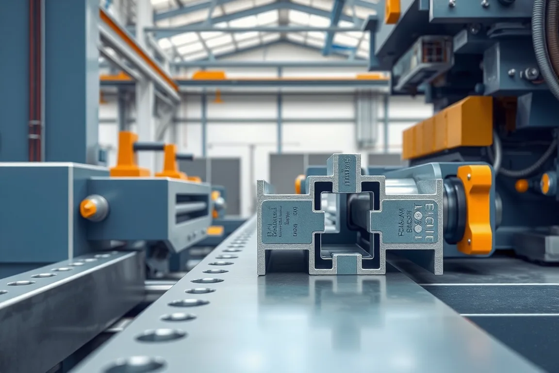
Custom profile tooling begins with a finished-part requirement and a plan for developing it from strip. The roller design is one element of that plan. Entry references, feature tools, cutoff, measurement and any later joining operation must work together to produce the approved component repeatedly.
Make the drawing suitable for tooling development
Identify the section, length range, functional datums and features that must fit another part. Separate critical interfaces from dimensions that are less important to the assembly. Include the drawing revision and the intended material combinations.
A sketch can begin a discussion, but the development baseline needs enough definition to assess the final result. Resolve ambiguous openings, returns and end details before they become unspoken assumptions in the tooling proposal.
Review the progressive forming sequence
The strip develops toward its final section through successive passes. Ask how the proposed sequence handles major bends, narrow returns and any asymmetry. The review should identify the difficult features and explain how trials will establish their acceptable production.
There is no universal stand count that proves a custom profile is well designed. Evaluate the sequence against geometry, material, surface condition and repeatability. More stands and a longer mill are not substitutes for demonstrated finished-part quality.
Consider access throughout the process
A return or partly closed shape can reduce access for later tools. Holes, embossments or joins may therefore need a particular sequence. Identify those dependencies early so that a feature is not assumed to be an easy addition after the main roll set is complete.
Review both physical tool access and the final measurement references. An operation that is convenient on flat strip must still produce the correct location and condition in the formed component. Keep the final datum requirements central to the decision.
Connect tool design to the material envelope
Pair each profile with its grade or alloy, thickness and surface requirements. State which combinations the tooling is intended to cover and which settings or components change. Avoid interpreting independent advertised limits as proof of every possible material-section combination.
Use production-intent material for meaningful validation. If development begins with a substitute, record what it can demonstrate and what remains to be tested. Keep coil identity and incoming measurements attached to trial results.
Evaluate the relaxed shape and functional fit
The finished component should be measured under the agreed support conditions after leaving the tools. Check section dimensions, straightness and relevant end behavior using consistent methods. A restrained in-process shape does not necessarily represent the delivered component.
For mating returns or interfaces, use controlled references to assess fit. Assembly checks are helpful alongside the required dimensional evidence. They should not conceal unacceptable forcing or local reshaping needed to make a sample connect.
Include feature and cutoff tooling in the design package
List tools for holes, slots, notches, marking and cutting as applicable. Show which part variants each tool supports. This prevents the forming-roll package from being mistaken for all the tooling needed to make the finished product.
Inspect cut ends separately from the middle of the profile. Local flare, crushing or burr condition can affect later assembly even when the continuous section is correct. Trial the actual length range and any special end pattern.
Plan how variants will share equipment
Some changes can use adjustment; others require replacement components or a separate roll set. Ask for a transition matrix that includes entry, forming, feature and cutoff tools. Similar outside sizes do not establish that two parts have interchangeable tooling.
Review tool storage, identification and handling. A modular arrangement is useful only if it can return to an accepted setup predictably. Include first-good-part checks when comparing the practical value of different change systems.
Make tool life and serviceability part of handover
Identify inspection and servicing responsibilities and the documentation supplied for replacement parts. Keep tool identities and revisions connected to the approved setup. Repairs or substitutions should trigger the applicable checks before accepted production resumes.
Avoid relying on undocumented corrections that only one operator remembers. A clear setup record, measurement method and accepted sample give the production team a repeatable reference and make later troubleshooting more efficient.
Select trials that challenge the right features
Choose cases that represent ordinary production and the important design boundaries. A narrow return, difficult material combination or feature near a bend may require attention even if it is not the largest profile. Explain the purpose of each trial part.
Include changes between relevant variants and examine the first accepted output after recovery. A successful long run on one setup does not prove the effectiveness of the shared-tooling strategy for a mixed product family.
Keep development decisions traceable
Record drawing changes, material changes, tooling revisions and the results supporting each accepted setup. Distinguish an engineering proposal from a demonstrated result. This makes it possible to understand which combinations are approved and which still need work.
When the project adds a new profile, compare it with the existing evidence instead of assuming that visual similarity is enough. The tooling review should identify new risks, additional parts and the validation needed to extend the production range responsibly.
Frequently asked tooling questions
Can tooling be designed from a photograph?
A photograph can explain appearance, but it does not define all dimensions, material and datums. Use a controlled drawing and relevant physical references for development and acceptance.
Is every profile change a complete tool replacement?
No. The appropriate arrangement depends on how the approved variants differ. Obtain a specific matrix of adjustments and replacement tools rather than a broad flexibility claim.
Why should the cutoff be reviewed with the rolls?
The customer receives cut components, not an endless profile. End condition, length and support can determine whether the formed section is usable in its next operation.
What demonstrates a repeatable setup?
A controlled tool and material identity, documented references, consistent inspection and accepted output after the required transitions. A single good sample without those records is a weaker basis for production.
Continue your research
- Custom & Industrial Profile Roll Forming Machines
- Custom Profile Roll Forming Machine
- Hat Channel Roll Forming Machine
- C Channel Production Line
- Z Channel Production Line
- Electrical Cabinet Frame Roll Forming Machine
- How Custom profile roll forming machine Works
- How To Choose a Custom profile roll forming machine
- Custom profile roll forming machine Price: What Affects the Cost?