
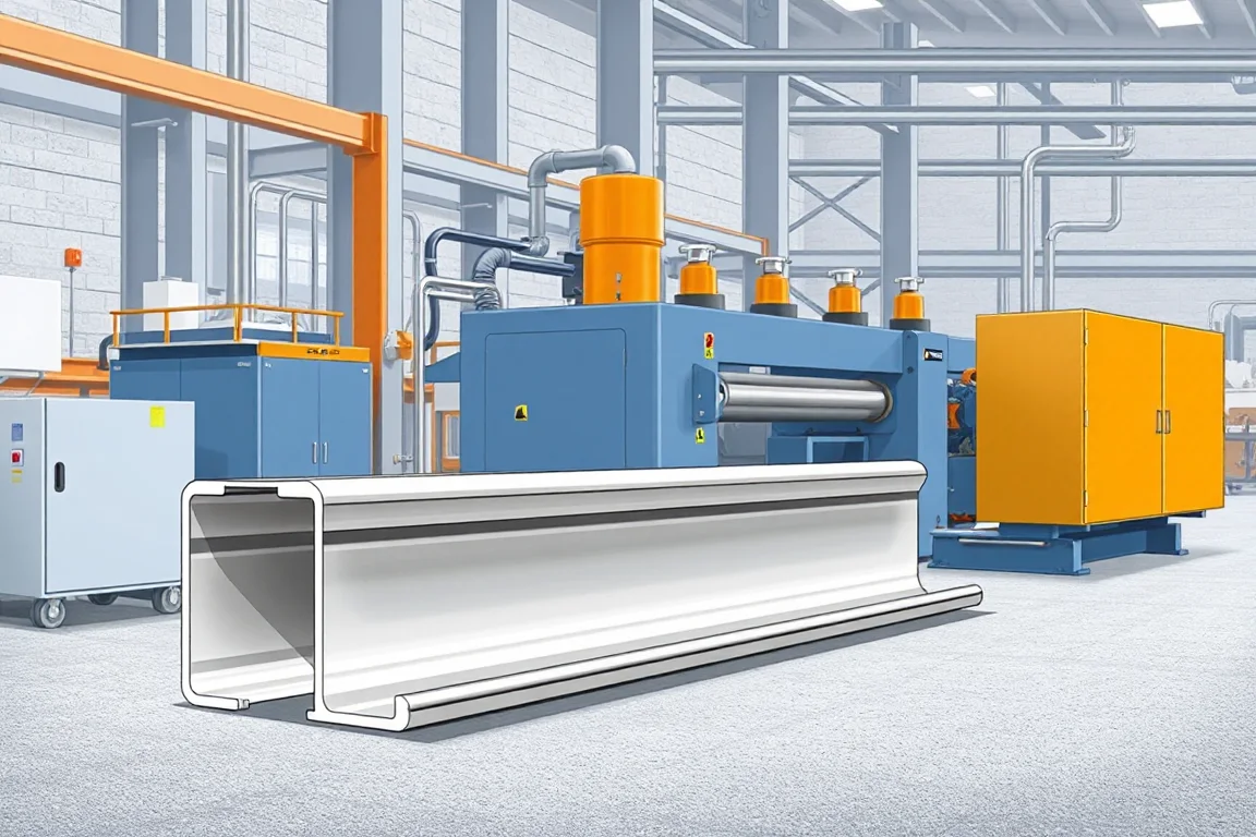
A custom profile roll forming machine produces a constant cross-section from strip by passing it through a progression of driven rolls. The machine is not defined by a generic capacity, but by the exact finished profile, the interfaces it must meet, and the agreed production route. This article explains how to define the finished part, evaluate process feasibility, choose tooling, plan secondary operations and inspect accepted output.
Define the finished profile, not just the outline
The starting point is a controlled drawing that shows the complete cross-section, including every bend, flange, stiffening feature, hole and cutout. More importantly, it should identify functional datums and mating interfaces. Not every dimension has equal importance. A pair of holes that receives fasteners, a tongue that slides into a housing, or a flange that seats against a panel are functional features. The angle or web dimension that merely separates them may be less critical. When a drawing does not distinguish these, the shop and the tool designer may allocate tolerances in a way that makes the part fit poorly.
Dimensions that define how the part assembles should be toleranced tightly enough to ensure function but not so tightly that they become impractical or unnecessarily costly. For example, the width between two mounting faces is likely a mating interface, while the radius on a non-seating bend may be a process outcome. The drawing should also state whether the profile is measured in a free state or a restrained state, because strip has residual stresses and the formed section may spring or close slightly after leaving the rolls. This measurement convention affects both tool design and acceptance inspection, and it should be documented before production begins.
Material, thickness and incoming strip variation
The strip material and its thickness range influence every aspect of the process: bend radius, springback, roll pressure and tool life. Steel, stainless steel and nonferrous strip each behave differently. Higher-strength steel requires larger bend radii and may need more forming stations; stainless steel often work-hardens, which changes the force needed in later passes; aluminium and other nonferrous metals can be softer but may mark easily. The buyer should specify base-metal thickness and grade, and also state the acceptable variation. Incoming strip thickness varies within a coil and from coil to coil, and that variation affects the final cross-section. If the machine must handle a range, the tooling and setup may need compensation, and the achievable profile tolerance may be wider than for a single fixed thickness.
Surface finish and coating also matter. Pre-painted or coated strip needs rolls that will not damage the coating, which may require different roll surface treatment or clearance. Bare steel may tolerate more aggressive forming but can rust if not protected after forming. The feasibility review should consider these factors together rather than treating the material as a single line item.
Feasibility review before tool count or power claims
A feasibility review is a structured engineering evaluation of whether the proposed profile can be formed from the chosen material by roll forming, and if so, what the forming progression should be. It examines the developed length of the strip, bend allowances, the sequence in which bends occur, and whether any feature is enclosed or re-entrant. Enclosed features, such as a hem or a return flange that folds back on itself, can restrict tool access. In those cases, the tool designer must decide whether to form the feature in a later station, use a special side roll, or move it to a secondary operation. The review also considers whether the profile can be cut off cleanly without distorting the section.
The outcome of a feasibility review is not a guarantee that the profile can be made on any machine; it is a judgment about a specific combination of profile geometry, material and process route. A fixed tool count or motor-power figure cannot be quoted responsibly before that review, because the number of forming stations depends on the complexity of the bends and the material behaviour. For some profiles, a feasibility trial with a partial tool set may be useful to confirm assumptions before committing to final tooling.
Tooling alternatives: dedicated rolls, adjustable and side tools
Roll tooling can be dedicated to one profile, adjustable to a family of similar sections, or arranged with side tools for features that cannot be formed by the main passes. Dedicated rolls are usually simpler to set and can produce a stable section at higher production rates, but they offer little flexibility if the profile changes. Adjustable tooling uses spacers, shims or movable roll positions to accommodate variations in width, flange height or material thickness. It can reduce the cost of a product family, but setup becomes more complex and the working range is limited by the machine structure and roll design.
Side tools, sometimes called auxiliary rolls or forming heads, act on the strip from the side rather than from top and bottom. They are used for bends that would otherwise require an impractical number of stations or for features such as outward-facing flanges, hems or curls. A side tool adds cost and setup complexity, but it may be the only way to produce a particular feature. Rotary or flying punches and dies for holes are another tooling choice; they can punch in-line as the strip moves, but they must be synchronised with the line speed and are usually justified when hole patterns repeat consistently.
When comparing tooling alternatives, consider not only the initial cost but also changeover time, setup scrap and the cost of future modifications. A cheaper initial tool set that cannot be adjusted may become expensive if the product family expands.
Production route from coil to finished part
The typical production route is feasibility review, coil preparation, progressive forming, secondary features and cutoff. Each step has its own requirements. Coil preparation includes loading the coil, feeding the strip, and possibly straightening or levelling it to remove coil set. A strip that is not flat entering the first forming station can produce a twisted or bowed section. Progressive forming uses a series of stations, each performing a small amount of bending, so that the strip gradually reaches the final shape without overstressing the material. The number of stations and the amount of bend per station are determined by the material and the profile geometry.
Secondary features include holes, slots, notches, embosses or tabs that are not formed by the main bending rolls. These may be produced by in-line punching, drilling, or by separate operations after the profile is cut to length. The choice depends on the feature, the production volume and whether the feature must be positioned relative to a formed datum. In-line operations can reduce handling, but they add tooling and maintenance complexity. Finally, cutoff separates the finished part from the strip. The cutoff method must support the profile without crushing or deforming it, and it must produce the required end quality. For some profiles, a shear cutoff may be adequate; for others, a saw cut or a die cut may be needed to avoid distortion. The cutoff can also include secondary operations such as notching or piercing the end.
Secondary operations and finished-part scope
A roll forming machine rarely produces a finished part in one continuous operation unless the part is simply a cut length. Most custom profiles require additional operations such as deburring, tapping, welding, inserting fasteners or assembly with other components. These operations may be performed in-line or off-line, and their cost and time must be included in the production plan. The equipment scope should clearly state which operations are integrated into the line and which are separate. If the line is expected to deliver a finished part, the supplier and buyer must agree on the complete sequence, including any manual steps, inspection points and packaging.
Separating operations can be beneficial when they require different skills, equipment or cleanliness. For example, welding may introduce heat that distorts the profile, so it might be better done after forming and cooling. Tapping may require access that is easier when the part is handled separately. The decision should be based on the functional requirements and the economics of the overall manufacturing flow, not just on the roll forming machine itself.
Changeover: dedicated versus flexible production
Changeover is the process of switching the line from one profile to another. It includes changing rolls, adjusting stations, changing cutoff tools and updating any in-line punching patterns. The frequency and batch size determine whether dedicated or flexible tooling is more economical. For high-volume production of a single profile, dedicated rolls and a fixed setup are usually efficient. For small, varied batches, the time spent on changeover can dominate the production time, and a high steady-state line speed may be less useful. In that case, quick-change tooling, preset adjustments and documented setup procedures can reduce downtime.
Changeover also affects setup scrap. Every time the line is adjusted, some material may be formed and discarded until the profile meets requirements. The amount of setup scrap depends on the complexity of the profile and the skill of the operator. When planning production, the buyer should ask how changeover steps are recorded and whether the settings are retained for repeat orders. A changeover that is not documented can lead to inconsistent quality and longer downtime on subsequent runs.
Inspection and accepted output
Inspection should focus on functional datums and mating features rather than tolerancing every dimension equally. The measurement method must be defined: whether the section is measured in a free or restrained state, which gauges are used, and how the part is supported during measurement. For example, a calliper reading across a flange may differ from a measurement taken with the part resting on a surface plate. The accepted output is not simply a number of parts per shift; it is parts that meet the drawing requirements and function in the assembly. First-off pieces should be inspected and approved before full production, and a representative steady-production sample should be checked to confirm that the process remains stable.
The inspection plan should also include the material and thickness, since these affect the final dimensions. If the line runs multiple materials or thicknesses, the acceptance criteria may need to be adjusted accordingly. Records of inspection results and any corrections should be kept, so that trends can be identified and corrected before they become problems.
Checklist for specifying a custom profile roll forming machine
- Provide a controlled drawing with functional datums and mating interfaces clearly identified.
- Specify base-metal material, grade and thickness range, including acceptable variation.
- State whether the profile is measured in a free or restrained state.
- Request a feasibility review before agreeing to a fixed tool count or motor power.
- Ask how each bend develops and whether any enclosed or re-entrant features restrict tool access.
- Decide which secondary features are formed in-line and which are separate operations.
- Confirm cutoff method, cut length requirements and end quality.
- Include changeover frequency and batch size in the economic evaluation.
- Agree on inspection methods, gauges and acceptance criteria before production.
- Run trials with the intended material and profile, not an easier substitute.
Comparing roll forming with other processes
Roll forming is one option among several for producing a custom profile. Press braking bends a flat sheet in discrete steps, which is flexible for low volumes and simple shapes but slower and less consistent for long, constant sections. Stamping can produce complex features and holes in a single stroke, but the tooling is expensive and best suited to high volumes. Extrusion creates a constant cross-section by pushing metal through a die, but it is typically limited to nonferrous metals and cannot easily incorporate bends from strip. Welded fabrication assembles a profile from separate pieces, which can be economical for large or low-quantity parts but introduces distortion and additional operations.
Roll forming is favoured when the profile has a constant cross-section, the bend development is suitable for progressive forming, and the production volume justifies the tooling. It is less suitable when the profile changes along its length, when the material is too brittle or too thick for the required bends, or when the order size is too small to amortise the tooling. A feasibility review should compare these alternatives and recommend the most appropriate process, not simply assume that roll forming is the answer.
FAQ
What information must be on the drawing for a custom profile?
The drawing should show the complete cross-section, including all bends, flanges, holes and cutouts. It should identify functional datums and mating interfaces, and state the material, thickness and any surface finish requirements. It should also specify whether dimensions apply in a free or restrained state, and which dimensions are critical for function.
Why is a feasibility review needed before a firm quotation?
A feasibility review determines whether the profile can be formed from the chosen material and what the forming progression should be. Without it, any tool count or power figure is an assumption. The review considers bend development, tool access, cutoff and material behaviour, and may recommend a trial before final tooling is committed.
How do I choose between dedicated and adjustable tooling?
Dedicated tooling is usually simpler and more stable for high-volume production of one profile. Adjustable tooling can accommodate a family of similar profiles and may reduce tooling cost, but it adds setup complexity and has a limited working range. The choice depends on production volume, changeover frequency and expected product changes.
What is the difference between in-line and separate secondary operations?
In-line operations are performed within the roll forming line, often saving handling time and improving consistency. Separate operations are done after the profile is cut to length, which can be more practical when the operation requires different equipment, access or cleanliness. The decision should consider the feature requirements, volume and overall cost.
How should I inspect a roll formed profile?
Inspection should prioritise functional datums and mating features. Use the agreed measurement method and gauges, and document whether the section is measured free or restrained. Check first-off pieces and a representative steady-production sample, and keep records so that trends can be detected.
What affects changeover time on a custom profile line?
Changeover time depends on the number of tools to be changed, the adjustment required, and whether settings are documented. Dedicated tooling may be faster to set for a single profile, while flexible tooling may require more adjustments. Batch size and frequency determine the economic impact.

Continue your research
- Custom & Industrial Profile Roll Forming Machines
- Hat Channel Roll Forming Machine
- Omega Profile Roll Forming Machine
- C Channel Production Line
- Z Channel Production Line
- Electrical Cabinet Frame Roll Forming Machine
- How Custom profile roll forming machine Works
- How To Choose a Custom profile roll forming machine
- Custom profile roll forming machine Price: What Affects the Cost?
Configuration & specification inputs
Match the configuration to your section drawing, material and production requirements.
| Parameter | Requirement / confirmation needed |
|---|---|
| Profile geometry | For a custom profile, provide a controlled drawing and explain which dimensions make the part function. A feasibility review should precede a fixed tool count or motor-power claim. |
| Material | Specified steel, stainless steel or nonferrous strip after feasibility review |
| Thickness & grade | Buyer to specify base-metal thickness and grade; operating range requires supplier verification. |
| Process route | Feasibility review → coil preparation → progressive forming → secondary features → cutoff |
| Cutting | Confirm profile-supported cutoff, cut lengths, end quality and any secondary operations. |
| Output | Define accepted output per shift with the actual profile and material. |
| Electrical supply | Buyer to state voltage / frequency / phase. Installed power requires a confirmed equipment schedule. |
| Acceptance | Use the intended material and controlled drawing for trials. Agree what is measured, how corrections are recorded and which settings are retained. Include a representative changeover if the line will make a family of related sections. |