
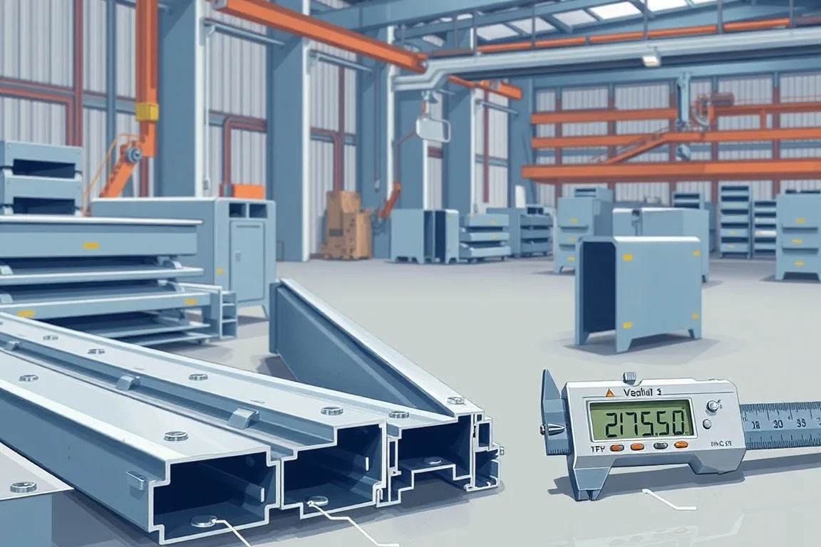
Material selection for a custom profile roll forming machine must connect the strip to the finished geometry. Thickness alone does not define the production requirement. Grade or alloy, material condition, coating, strip width, edge quality and the section's functional features all belong in the brief used to develop and validate the line.
Describe the incoming strip unambiguously
Identify the material designation and the condition in which it will be supplied. Include the applicable purchase specification and required supplier records. A description such as steel or aluminum is too broad to establish the forming and inspection basis for a custom component.
Keep coating and surface-protection information separate from the underlying material. State which face will be visible and which surfaces become mating or joining interfaces. These details influence what should be inspected after forming, cutting and normal handling.
Pair thickness with each grade and profile
Build a matrix in which each row identifies a section, material and thickness combination. Add the strip width and important feature operations. This is more informative than independent minimum and maximum values that appear to describe every possible combination.
Mark required launch combinations and possible future combinations differently. The proposed tooling and trial plan should state what has been reviewed, what will be demonstrated and what remains outside the approved scope. Avoid expanding that scope through assumptions after the equipment has been ordered.
Distinguish base-metal and finished thickness
For coated material, state which thickness definition is being used. Keep the units and measurement reference consistent across drawings, purchasing and machine discussions. A nominal commercial description can otherwise be mistaken for the base-metal value used in an engineering assessment.
Record the agreed incoming tolerance and inspection method. The aim is not to prescribe a universal tolerance in a generic guide, but to ensure that the equipment development uses the material variation the project actually permits.
Connect strip width to developed geometry
The incoming width supplies the material for the finished web, flanges, returns and bends. It should be established through the approved part and tooling development rather than by adding visible outside dimensions without considering the bends.
Ask how strip-width variation and edge condition will be controlled. Where an edge becomes a mating return, joining edge or exposed feature, its condition may matter beyond the overall width measurement. Include the incoming strip requirements in the coil purchase brief.
Review bends and openings with the actual material
Narrow returns, local features and difficult access can make a custom section more demanding than a plain channel of the same overall size. Discuss these areas explicitly with the tooling designer. The material trial should represent the relevant geometry, not merely demonstrate that a flat strip can be bent.
Inspect the relaxed section and the important surfaces after the full route. A part held inside tooling can look different from the finished component, and a later cutoff or joining operation may introduce a condition not visible during forming alone.
Treat different metal families as separate cases
Do not transfer an accepted setup from one metal family to another without review. Grade, alloy and material condition can change the process response and surface requirements. The same nominal section and thickness do not make every material interchangeable.
If several materials are planned, obtain a clear tooling and setup strategy for each. Record whether the proposal uses shared tools, different settings, replacement components or separate routes. Keep the demonstrated combinations attached to the accepted samples.
Include features, joins and finishes in material trials
Holes, slots, cut edges and joining preparation should be assessed on the intended material. Their final location and condition may be essential to assembly. A successful plain-profile sample leaves those requirements unresolved.
Where the part receives a later finish or joining process, identify the responsible specification and approval step. Confirm that the formed and cut component is suitable for that operation. Do not assume downstream processing will conceal or correct an unacceptable incoming surface.
Define a representative trial matrix
Select normal production cases and meaningful boundary cases with the responsible technical team. The hardest case is not necessarily the thickest material: a particular return, surface condition or feature can drive a separate risk. Explain why each selected sample belongs in the trial.
Retain coil identities, measured incoming information, setup references and final results. If a substitute material is used, document the difference and the question that remains open. This prevents an early development sample from becoming an accidental approval of a wider range.
Control material changes during production
A new supplier, revised purchase specification or different coating can warrant review even when the nominal part drawing is unchanged. Use the project's change-control and first-part requirements to decide what evidence is needed. Keep the reason for any setup adjustment with the material record.
When a dimensional problem appears after a coil change, verify the incoming material and measurement method before assigning the cause to tool wear. The useful diagnosis compares evidence from both sides of the transition.
Turn the material brief into a shared reference
The final brief should connect purchasing, equipment development and inspection. Include the material matrix, units, thickness definition, strip requirements, surface expectations and trial boundaries. Use the same reference in quotation discussions and acceptance records.
That shared basis makes a custom project easier to manage. It does not replace the supplier's engineering assessment; it ensures that the assessment answers the intended production requirement instead of a loosely described material range.
Frequently asked material questions
Is maximum thickness enough to specify the machine?
No. Pair thickness with the grade, section, width and features. Separate limits do not prove that every combined condition is suitable for the proposed line.
Can a profile use the same strip width in every material?
That must be reviewed through the approved development and final geometry. Do not treat a width from one accepted material and setup as a universal value.
Should coated surfaces be checked only before forming?
No. Inspect the required surface after forming, feature operations, cutting and normal handling. The saleable component must retain the agreed finish through the complete route.
What should accompany an accepted trial sample?
The drawing revision, material and coil identity, thickness definition, incoming checks, setup reference and final inspection results. These records explain what the sample actually demonstrates.
Continue your research
- Custom & Industrial Profile Roll Forming Machines
- Custom Profile Roll Forming Machine
- Hat Channel Roll Forming Machine
- C Channel Production Line
- Z Channel Production Line
- Electrical Cabinet Frame Roll Forming Machine
- How Custom profile roll forming machine Works
- How To Choose a Custom profile roll forming machine
- Custom profile roll forming machine Price: What Affects the Cost?