
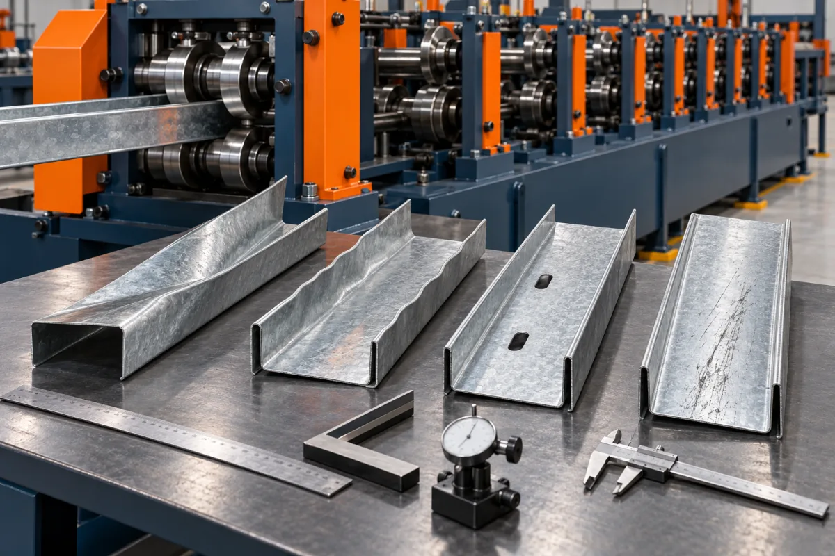
Purlin troubleshooting should distinguish section geometry, connection features, end condition and part identity. A member can fail its intended use even when one of those categories is correct. The most effective investigation starts with the approved drawing and an identified sample, then locates the first process boundary where the deviation appears.
Record the member before changing the setup
Identify the section revision, material coil, length, hole pattern and part mark. Note the configuration and recent size or C/Z changes. Retain a baseline sample and measured results so a later correction can be compared with the original condition.
Describe the actual deviation: unequal flange, incorrect lip, twist, misplaced hole, end flare or another measured issue. The phrase bad purlin is too broad to guide useful work. Use the drawing's datums and agreed support condition.
When flange or lip dimensions are incorrect
Confirm the intended section combination and developed strip width. A familiar web size does not prove that the flanges and lips match the required version. Compare the installed tooling and setup references with the correct drawing revision.
Check whether the issue follows a material or size change and whether both ends and the center show the same result. Qualified personnel can then investigate the relevant material, guidance or forming condition under the equipment's procedures.
When the member twists or bows
Inspect in the agreed support condition and distinguish longitudinal bow, twist and local deformation. A long member resting differently can appear to have changed shape even when the measurement method is the cause of the apparent difference.
Compare incoming strip records, forming samples and the member after discharge. Handling can introduce damage after correct forming. Do not change tools to compensate for an unidentified downstream problem, and do not assume every shape issue originates in the coil.
When holes are in the wrong position
Check the final-member datum, reference end and face orientation. A punch can produce a clean feature at the wrong coordinate. Compare the approved part data with the production instruction and the measured component.
Determine whether the error is constant, changes with length or appears after a particular setup transition. Record individual requested and measured positions. Avoid informal offsets that conceal an unexplained error and may create a new one on another part.
When punching quality changes
Record the material grade and thickness, feature identity and observed condition. Inspect tooling and scrap-related issues only through the approved isolated procedure with qualified personnel. Do not treat a feature-condition issue as automatically equivalent to a location error.
Compare the result across the relevant material combinations. A change in incoming material can alter the feature-making task. Any tool service or process correction should be verified on the final member, including its positional relationship to the formed section.
When ends flare or become locally distorted
Measure both ends and compare them with the central cross-section. Identify the cutting route and correct section-specific components. Determine whether the deviation is present immediately after production or appears during discharge and stacking.
A central template check alone cannot clear the member. End geometry can affect connections and nesting even when the middle meets dimensions. Record the support and measurement method so trials and production checks remain comparable.
When a C/Z or size change produces the wrong part
Verify the complete configuration: forming orientation, dimensions, punch references, cutoff components and part data. An automated movement may complete successfully while another required setup item remains incorrect.
Use the first-off approval process before releasing the batch. If an error is discovered later, trace the affected production interval using order and setup records. A corrected new member does not automatically clear the parts produced under the earlier condition.
When correct members receive incorrect identification
Separate physical manufacturing quality from data and labeling quality. Check part marks, drawing revisions, units and bundle assignments. Similar-looking sections can carry different connection patterns, making identification errors difficult to detect by appearance alone.
Follow the information through each transfer and handling boundary. If identity is lost at stacking, a forming adjustment cannot solve it. Correct the workflow and verify a controlled mixed order before relying on the revised process.
Run a controlled correction and full-member verification
An illustrative mixed-package error is a correctly formed Z member carrying the mark of a similar C member. Measuring only web and length may not reveal the information failure before shipment. Compare orientation, feature pattern and mark together, then trace the labeling or data boundary. This example explains why the troubleshooting record should not end once the cross-section looks good. The component must be physically correct and assigned to the correct building position.
Preserve the baseline, identify the authorized change and check the complete product afterward. Improving one flange dimension while worsening twist or hole position is not a successful recovery. Use representative lengths and the actual material combination.
- Confirm the defect against the approved member drawing.
- Locate the earliest process stage where it is present.
- Review material, setup, tooling and data changes.
- Apply the approved action through qualified personnel.
- Verify section, features, ends and part identity.
- Record the cause, release decision and preventive work.
Frequently asked purlin troubleshooting questions
Should twist always be corrected at the last forming stage?
No universal adjustment follows from that symptom. Incoming material, earlier forming and handling need to be distinguished. Use a controlled investigation and the equipment maker's procedures.
Why can a hole pattern look correct but fail at assembly?
Its datum, reference end or face orientation may be wrong, or another member dimension may differ. Check the complete drawing relationship rather than hole spacing alone.
Does a successful automated changeover prove the first part is good?
No. It proves that the programmed movement completed. The member still needs the required geometry, feature, end and identification checks before release.
What evidence should accompany a support request?
Send the member and feature drawings, coil identity, setup history, annotated measurements and samples from relevant process stages. Include both ends and the center when reporting shape issues.
Continue your research
- Purlin Roll Forming Machines
- C Purlin Roll Forming Machine
- Z Purlin Roll Forming Machine
- 80-300mm CZ Purlin Roll Forming Machine
- 100-400mm CZ Purlin Roll Forming Machine
- Automatic Size Change CZ Purlin Machine
- How Purlin roll forming machine Works
- How To Choose a Purlin roll forming machine
- Purlin roll forming machine Price: What Affects the Cost?