
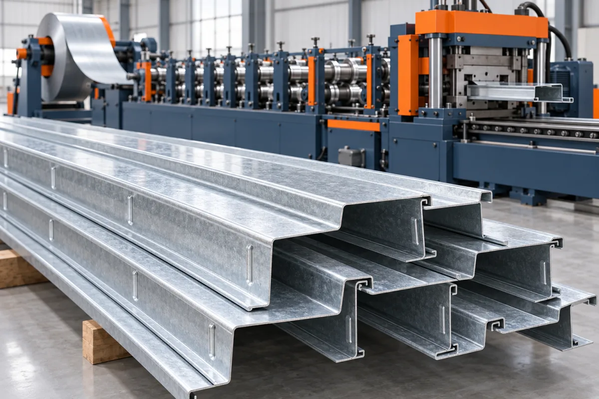
A sigma purlin roll forming machine produces the particular multi-bend structural section defined by the selected sigma-profile drawing. Unlike a plain web with simple opposing or same-side flanges, a sigma section includes additional shaped web features that must be developed and measured as part of the whole member. The name identifies a profile family, not a universal set of dimensions.
The production brief should connect web offsets, flanges, lips, material and connection features. A useful equipment comparison explains how that geometry is formed, how tools and hole positions change across the requested sizes, and how the finished component is inspected after cutting and handling.
What makes a sigma section a distinct tooling task?
The additional bends or offsets create more geometric relationships than a simple channel outline. Their positions influence the section's reference surfaces and the way it fits its connections. They also affect how the strip develops progressively through the roll tooling.
Start from the controlled cross-section rather than drawing a generic sigma symbol. Show every bend, return and functional dimension. Two similarly named sections may have different offset geometry, lips or connection arrangements and therefore need different tooling and approval references.
Which production scope is being requested?
One defined sigma section
A stable section with varying lengths and hole programs creates one type of production requirement. The main questions concern material, feature positioning, cutting and repeatable output around that geometry.
A family of sigma sizes
List the combinations of web depth, offsets, flanges and lips required by the product design. Identify which dimensions change together. A nominal depth range does not establish that every internal feature can be adjusted independently.
Sigma and other structural profiles
If the line must also make C or other sections, define those drawings and transitions separately. Some equipment arrangements support specified multiple profiles, but that capability must be part of the proposed tools and process, not inferred from the word purlin.
What belongs on the section and connection drawings?
Use datums that relate to the member's actual function. For a more complex section, the easiest outside surface to measure is not necessarily the right reference for a connection hole or mating component. Agree the support and measurement method before deciding whether a trial member is acceptable.
- Web depth, offset geometry, flanges, lips and bend radii.
- Material grade, strength requirements, thickness and coating.
- Hole and slot geometry, with clearly identified references.
- Finished lengths and the relationship of features to both ends.
- Required straightness, twist and local end-condition checks.
- Connection components and the assembly used for trial approval.
Keep the drawing revision with the order program and reference sample. A familiar size label should not hide a changed offset, lip or hole pattern.
How does the line develop the sigma geometry?
- Prepare the material: identify the coil and establish the required loading and entry condition.
- Create specified features: punch or otherwise produce holes and notches at the stage defined by the proposed route.
- Develop the section progressively: form the web features, flanges and returns through the roll sequence.
- Cut to length: use a supported arrangement appropriate to the complete section.
- Discharge and identify: handle members without masking or introducing geometric deviations.
- Inspect: measure the functional datums and trial the required connection.
Ask how the forming sequence maintains access to each feature and how the section is supported at later operations. The number of forming stations alone does not explain whether the approved sigma geometry can be reproduced in the specified material.
How are punching and web offsets coordinated?
Hole location must remain meaningful after the web is formed. Establish whether the feature is referenced to a flat-strip dimension, a finished-section datum or a cut end, and how the proposed route delivers the final requirement. The manufacturing program and inspection drawing should agree on that interpretation.
For each size, identify punch tools, access and support requirements. A nominally adjustable forming section does not automatically relocate every hole-making operation. Include die changes and first-off checks in the size-change description.
Use the actual mating connection to confirm the result where applicable. A hole can be present and dimensionally neat while still being wrong relative to the offset geometry or the intended end reference.
What does a meaningful size-change matrix show?
List each required complete section, material combination and feature program. Then identify the adjustments, replacement tools, guides, cutting components and programs needed to move between them. This makes the difference between an operating range and an unsupported universal-profile claim visible.
Demonstrate important combinations, including those that are demanding within the agreed range. Finish the changeover assessment with an accepted member and correct connection features. Record setup material and any recovery work before stable production.
A return to an earlier configuration is useful evidence for repeat orders. Preserve the relevant settings and physical references by drawing revision so the process can reproduce the same component later.
How should material and springback be reviewed?
Pair thickness with material grade or strength, width and the full section. The behavior of the bends after release from the tooling depends on that combination. A trial in easier material does not demonstrate a more demanding production requirement.
Inspect trial members in the agreed free or supported condition. Avoid holding a section into the desired shape and then reporting those dimensions as its normal output. Record material identity, setup and measurement conditions together.
Any material substitution also needs to respect the component design. A machine's ability to form a visually similar section from another stock does not establish structural equivalence.
What should cutting, handling and inspection support provide?
The completed sigma profile needs suitable support through cutoff and discharge. Inspect both ends and compare geometry before and after the relevant operations where necessary. Local distortion at a cut should not be mistaken automatically for an error throughout the entire roll-formed section.
Agree how long members will be located for straightness and twist checks. The section may not sit naturally on an arbitrary flat surface in a repeatable way. An inspection method with defined references is more useful than selecting whichever position makes a sample appear straight.
Include identification and package requirements in the handling review. Similar-looking sizes or hole patterns should remain traceable to their intended orders after stacking.
How should investment and output be compared?
Use the same sigma-section matrix and connection requirements in every quotation. Include the required roll tools, punching, cutting, coil handling and discharge. Any capability for additional C or other profiles should have its own documented tooling and changeover scope.
Compare accepted members over the actual length and feature mix. Changes in size, dense hole programs and unloading can matter more than a peak strip speed. Keep setup rejects and production deviations visible in the trial record.
For a mixed structural-profile business, assess how a shared line would schedule the orders. Flexibility can be useful, but it may also place several product families on the same resource. Compare that workflow with dedicated equipment rather than choosing from the number of advertised profiles alone.
What should a sigma purlin trial prove?
- Confirm all cross-section features and the material specification.
- Measure web offsets, flanges and lips from the approved datums.
- Check holes and slots against the finished-section and end references.
- Inspect cut ends and the agreed straightness and twist conditions.
- Assemble the relevant connection using intended components.
- Run a required size change and recover an accepted member.
- Review normal handling, identification and accepted-output records.
The trial verifies a manufacturing target. Structural performance belongs to the designed member and its use within the relevant system, not to the number of bends or the machine's ability to adjust its web depth.
Frequently asked questions
Is a sigma section just a C purlin with another name?
No. Its defined web features and geometric relationships need their own drawing and tooling review. A general purlin-machine description does not establish the ability to reproduce a particular sigma section.
Can one line make both C and sigma profiles?
A suitably designed configuration may cover specified profiles. Request the exact tool schedule and a complete changeover demonstration. Do not infer the capability from a broad adjustment range or another supplier's machine description.
Which surface should be used to locate holes?
Use the functional datums on the approved component drawing. The responsible design and manufacturing teams should agree how those references are realized and inspected. An arbitrary outer edge may not represent the intended connection.
Does the extra web shaping guarantee better structural performance?
No general conclusion should be drawn from appearance alone. Performance depends on the complete section, material, connections and design conditions. The forming equipment is selected to manufacture that specified component.
Why is the inspection support condition important?
Complex long sections can appear different depending on how they are supported or restrained. A defined method makes measurements comparable and avoids accepting a shape only because a fixture forces it into position.
What should accompany the first enquiry?
Provide complete section and connection drawings, material combinations, lengths and the required variant schedule. Include inspection datums and mating components where useful. These establish the tooling and acceptance task clearly.
Define every functional bend before comparing machines
The value of a sigma line is its ability to reproduce the intended multi-feature member with the correct connections and handling condition. Use the complete drawing and production mix as the selection basis. That approach makes adjustment, tooling and output claims testable against a specific product.

Continue your research
- Purlin Roll Forming Machines
- C Purlin Roll Forming Machine
- Z Purlin Roll Forming Machine
- 80-300mm CZ Purlin Roll Forming Machine
- 100-400mm CZ Purlin Roll Forming Machine
- Automatic Size Change CZ Purlin Machine
- How Purlin roll forming machine Works
- How To Choose a Purlin roll forming machine
- Purlin roll forming machine Price: What Affects the Cost?
Configuration & specification inputs
Match the configuration to your section drawing, material and production requirements.
| Parameter | Requirement / confirmation needed |
|---|---|
| Profile geometry | A sigma section includes additional web bends. Those bends change the forming sequence and inspection datums; it should not be quoted as an ordinary C purlin solely because the external depth is similar. |
| Material | Specified galvanized or uncoated structural steel grade |
| Thickness & grade | Buyer to specify base-metal thickness and grade; operating range requires supplier verification. |
| Process route | Payoff → leveling → punching/notching → adjustable forming → cutoff → dimensional inspection |
| Cutting | Confirm profile-supported cutoff, cut lengths, end quality and any secondary operations. |
| Output | Define accepted output per shift with the actual profile and material. |
| Electrical supply | Buyer to state voltage / frequency / phase. Installed power requires a confirmed equipment schedule. |
| Acceptance | A sigma profile can require a substantially different bend sequence. When comparing a dedicated machine with a proposed conversion, list the rolls, guides, punch tools and cutoff support involved. Confirm the time and verification needed to return to the previous profile. |