
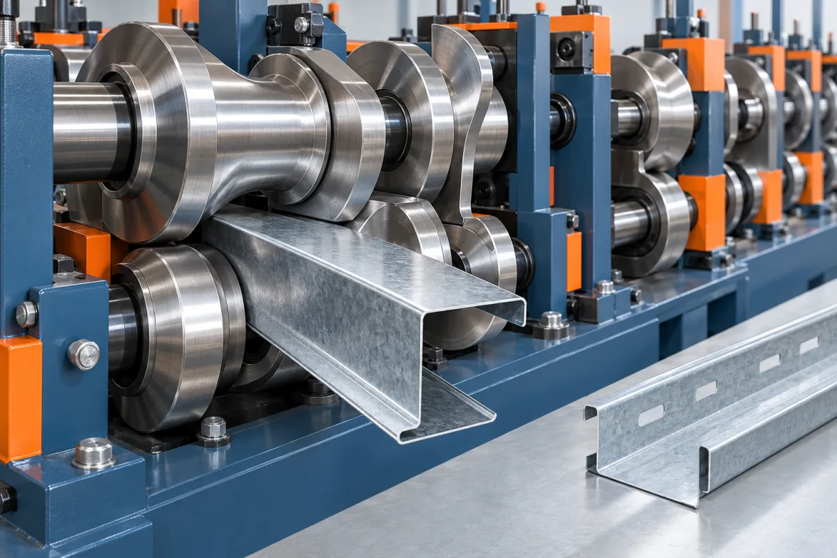
Purlin tooling must control the web, flanges, lips and their relationship to connection features across the required section range. A combination C/Z line adds the challenge of recovering those relationships after size and orientation changes. The tooling review should focus on complete accepted members, not only on a central cross-section.
Define the full geometry envelope
Provide actual section combinations with web, flange, lip and bend details. Independent minimum and maximum dimensions can imply combinations that are neither required nor feasible on the proposed arrangement. Use a member matrix to make the intended range explicit.
Include the longitudinal drawing with holes, notches and length references. Even when feature tools are separate from forming rolls, their output must agree on the final member. The datum scheme links those operations.
Review progressive development for the actual material
The strip reaches the final section through intermediate forms. The tooling concept must account for the specified grade, thickness and geometry combinations. Ask the designer to explain the difficult cases and the trial evidence used to validate them.
Do not judge capability by station count alone. The sequence, adjustment concept and material envelope matter. A tool set that produces one convenient section does not establish the full catalog unless the relevant combinations have been reviewed.
Distinguish C-to-Z conversion from size adjustment
Changing flange orientation and changing section dimensions are different tasks. A proposal should explain how each is achieved and identify manual components or checks. Automatic conversion does not necessarily mean every size and lip combination is available without additional parts.
Request a transition matrix for the products important to the business. Include guides, forming references, punch settings and cutting components. The practical tooling envelope becomes much clearer when described as real transitions rather than marketing labels.
Coordinate punch tools with final-member datums
Holes and slots may be made before or at another defined stage relative to forming. The tooling plan must ensure their final positions meet the member drawing. Specify feature orientation and reference end so a correct local hole is not placed on the wrong face or from the wrong datum.
Check feature access across the size range. A punch arrangement suitable for one web or flange does not automatically reach every requested location. Identify special tools or offline operations before finalizing the line scope.
Include cutoff geometry and end behavior
Review the proposed cutting route with the section and material range. Inspect complete members for end flare, local distortion and cut condition. A central coupon can confirm profile geometry while missing a critical end problem.
Section-specific cutting components need clear identification. Where the arrangement supports multiple sizes, ask what changes and what remains common. Keep those parts associated with the correct profile revision in the setup record.
Make the inspection condition explicit
Long members require defined support and measurement references. Agree how web, flanges, lips, straightness and twist are assessed. Comparing a restrained sample with a freely supported one can create misleading conclusions about tooling performance.
Use complete-member checks alongside section measurements. The final product must connect and handle as specified, not simply match a short cross-section template. Record both ends and relevant positions along representative lengths.
Test the combinations that challenge the design
The trial matrix should include meaningful boundaries in geometry, material and feature work. Ask why each sample was selected. The largest web alone may not be the most informative case if another combination has more demanding flanges, lips or punching.
- A common production section for baseline recovery.
- A required geometry and material boundary.
- A member with important feature locations.
- Short and long lengths for end and handling checks.
- A size or C/Z transition relevant to scheduling.
- A return to a previously accepted configuration.
Recover a previous setup to prove repeatability
A one-way change demonstrates that equipment can move to another condition. Returning to the first accepted product tests the usefulness of tooling references and setup control. Measure the recovered member and its features using the same method as before.
Record first-good-member time and rejected starts. These values help compare tooling arrangements in a business with frequent changes. They also identify where documentation or training needs improvement before production begins.
Control future section changes as engineering work
For example, keeping the web unchanged while increasing a lip is not merely a cosmetic revision. It changes the complete section and potentially its developed strip width, forming path and inspection references. The structural drawing, tool review and incoming-material specification should remain coordinated. If a supplier proposes obtaining the new section through adjustment alone, request the supported configuration and an accepted trial rather than treating the unchanged web dimension as proof. This small-change scenario is useful during procurement because it exposes how the tooling system handles real product evolution.
A changed lip, flange or hole position can affect several tools and inspection references. Review the complete member rather than making an isolated adjustment to satisfy one dimension. Keep the approved drawing, tool identity and setup record aligned.
Ask which future changes are supported by adjustment and which require new tools or a separate feasibility review. This boundary is more useful than a promise that the machine is universal. It protects both the equipment investment and the consistency of the building components.
Frequently asked purlin tooling questions
Does automatic C/Z conversion mean no manual work remains?
Not necessarily. Other size, feature or cutting changes may still require manual tasks and inspection. Request the complete transition sequence for the actual member catalog.
Can web size alone define a purlin tool set?
No. Flanges, lips, bends, material and connection features must also be considered. Use complete drawings and required combinations.
Why inspect end flare separately from the center?
The ends can behave differently through cutting and forming. A central cross-section does not establish that the complete member meets its connection and handling requirements.
What demonstrates a useful flexible tooling system?
Accepted members across the defined range, including feature and end checks, plus repeatable recovery after real configuration changes. Movement speed alone is not sufficient evidence.
Continue your research
- Purlin Roll Forming Machines
- C Purlin Roll Forming Machine
- Z Purlin Roll Forming Machine
- 80-300mm CZ Purlin Roll Forming Machine
- 100-400mm CZ Purlin Roll Forming Machine
- Automatic Size Change CZ Purlin Machine
- How Purlin roll forming machine Works
- How To Choose a Purlin roll forming machine
- Purlin roll forming machine Price: What Affects the Cost?