
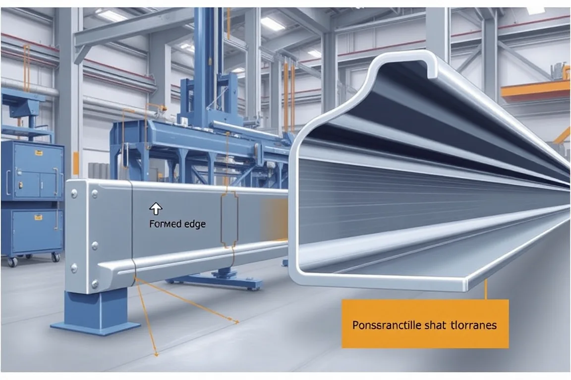
Guardrail roll forming machine troubleshooting is not a hunt for one failing component. Finished beam defects usually emerge from interactions among incoming coil, leveling, punching, progressive forming, cutoff, coating sequence and downstream handling. The practical goal is to locate the stage where a deviation first becomes measurable and to decide whether the fault belongs to material, tooling setup, machine condition or part handling. This guide explains what each defect family means, what evidence to collect, and how to keep component acceptance distinct from system-level approval.
Why beam defects rarely have a single cause
A formed guardrail beam passes through a chain of operations. Coil is uncoiled and leveled, then punched for splice holes or slots, progressively bent through a series of roll passes, cut to length and handled. Each stage can introduce or mask dimensional change. A wave that looks uniform at the exit may have been created early and disguised by later passes. A hole that appears misplaced may reflect end reference rather than punch position. Troubleshooting therefore starts by identifying the first stage where the part visibly departs from the approved drawing.
Material behaviour compounds this. Steel grade, base-metal thickness and coating condition affect springback, hole quality and edge condition. When coil lot changes, the same machine settings can produce a different result. That is not automatically a machine fault; it is an interface between material and forming process that must be evaluated with the drawing and purchase specification in hand.
Symptoms that point to material or setup changes
When a defect appears suddenly after a coil change, material variation is a primary suspect. Wave height, angularity and hole quality can shift if thickness, yield behaviour or coating differs from the previous lot. The useful evidence includes the coil identity, mill certificate information available to the buyer, the previous good part and the first suspect part measured under the same conditions.
When a defect appears after a setup change, the setup itself is under scrutiny. Roll gap, pass alignment, punch timing and cutoff reference are common areas to verify against the equipment manufacturer's procedure. A useful discipline is to change one controlled variable at a time, record the result, and compare against a retained known-good part. That approach prevents the common error of adjusting several stations at once, which obscures which change actually mattered.
Incoming strip and coating sequence
Guardrail systems are often specified with a protective coating, and the sequence matters. Forming may occur before or after coating depending on the approved process. When edges are punched or cut, exposed steel may require treatment according to the coating specification. If the coating process is not agreed in the purchase specification, troubleshooting becomes ambiguous because some surface and edge conditions are not forming defects at all.
For dimensional troubleshooting, record whether measurement happened on bare or coated material, because coating can affect apparent thickness, hole edge condition and surface appearance. The material grade and coating process belong in the purchase specification, not in an improvised adjustment decision.
Forming defects: wave geometry and lap fit
Wave geometry is the core functional shape of the beam. If waves are shallow, angular or inconsistent, the cause may sit in leveling, roll pass alignment, roll wear or springback behaviour of the current material. Wave irregularity along the length points toward strip tension, leveling or pass-to-pass inconsistency. Wave irregularity across the section points toward roll gap, tooling condition or asymmetric loading.
Lap fit matters when beams overlap at splices. If the lap is tight, loose or mismatched, the interaction between wave geometry, material thickness and hole position should be examined. Bending a sample into place can hide a production issue instead of resolving it. The accepted reference is the approved drawing and the specified lap orientation, not what makes one joint fit on the floor.
Punching and splice-hole position
Splice-hole position is a functional dimension. Hole pitch, edge distance and slot orientation affect how beams connect. When holes appear misplaced, the diagnosis should separate punch die condition, punch timing relative to strip position, end reference and cutoff length. A beam cut short will shift every hole relative to the leading end even if the punch itself is correct.
Useful evidence includes hole pitch measured from a consistent datum, end reference, burr condition and whether the deviation is constant or progressive. A constant offset points toward reference or setup. A progressive change suggests strip slip, accumulating length error or a drift in the feeding or cutoff system.
Cutoff, length and end quality
Cutoff quality affects both length and downstream assembly. Confirm that the cutoff is profile-supported and suitable for the section, because an unsupported cut can distort the end, close the section or produce an unacceptable burr. Cut length should be measured from the designated datum, not from whichever end is convenient.
If end quality varies, examine cutoff timing, blade condition and whether the strip is moving when the cut occurs. Some processes include secondary operations such as end treatment or hole finishing; these should be defined in the purchase specification so that acceptance criteria are clear.
Building a diagnostic evidence trail
Reliable troubleshooting depends on disciplined records. Document the part identity, coil lot, drawing revision and measurement conditions for every suspect part. Keep a known-good reference part and use the same measurement method across comparisons. Compare incoming material, output before cutoff where it is safely observable, and the finished handled part.
This trail answers the central question: where did the deviation first appear? If the strip is good before forming and the wave is good before cutoff, the fault may lie in cutoff or handling. If the deviation exists before cutoff, the forming or punching stages deserve attention. The evidence narrows the scope without guesswork.
Safe troubleshooting boundaries
Do not reach into running machinery or improvise adjustments around stored energy, including hydraulic, pneumatic or mechanical accumulators. Any change to guarded zones, interlock systems or qualified processes should be escalated to the responsible engineer. Adjustments to moving machinery should follow the equipment manufacturer's procedure, with the machine in the state that procedure requires. The purpose of this boundary is not bureaucracy; it is that uncontrolled intervention can create both injury risk and a false troubleshooting signal.
Checklist for structured fault finding
- Record whether the fault started at a coil change, setup change or neither.
- Capture part identity, coil lot, drawing revision and measurement conditions.
- Separate forming effects from cutting, joining and handling effects.
- Retain a known-good reference part and use the same measurement method.
- Compare incoming material, pre-cutoff output where safely observable, and finished part.
- Verify hole pitch, end reference and lap orientation against the approved drawing.
- Confirm whether forming occurs before or after protective coating and how punched or cut edges are treated.
- Change one controlled variable at a time under the equipment manufacturer's procedure.
- Escalate safety-related or qualified-process changes to the responsible engineer.
- Keep component dimensional acceptance separate from system crash-testing and installation approval.
Comparing alternatives for correction
When a defect is confirmed, several correction paths may exist, and they differ in scope. A setup correction addresses alignment, timing or reference without changing hardware. A tooling correction addresses roll wear, punch die condition or cutoff blade condition. A material correction addresses incoming coil conformance or coating sequence. A process correction addresses the sequence itself, such as when coating occurs.
The tradeoff is traceability. Setup corrections are usually fastest to trial but must be documented so that the known-good condition can be restored. Tooling corrections may require spare-part planning and re-qualification of the affected station. Material and process corrections extend beyond the machine and should be handled with the party responsible for the purchase specification. Choosing a path without evidence tends to repeat the same defect under a different description.
FAQ: guardrail roll forming machine troubleshooting
What should I check first when beam wave geometry changes?
Establish whether the change began with a coil lot or a setup change. Then compare a retained known-good part with the suspect part using the same measurement method and datum. If the deviation is present before cutoff, focus on leveling, forming and punching. If it appears only after cutoff or handling, examine those stages first.
Why do splice holes look misaligned even when the punch seems correct?
Hole position is measured relative to an end reference. A change in cut length, end datum or strip position shifts every hole without any punch fault. Verify hole pitch from a consistent datum, check end reference and cutoff length, and confirm lap orientation against the approved drawing rather than forcing a joint to fit.
Can I correct a tight or loose lap by bending the beam into place?
Bending a sample into place can hide a production issue instead of resolving it. Lap fit depends on wave geometry, material thickness and hole position. Measure those dimensions and compare them with the drawing. If the lap still does not conform, the deviation should be treated as a component acceptance issue, not corrected by field deformation.
How do I know whether coating is contributing to a defect?
Check whether forming occurs before or after protective coating and how punched or cut edges are treated. Coating can affect surface appearance and edge condition, and an unagreed coating sequence makes it hard to separate a forming defect from a coating condition. The material grade and coating process belong in the purchase specification.
What evidence should I collect before adjusting anything?
Collect part identity, coil lot, drawing revision and measurement conditions. Keep a known-good reference, record where the deviation first becomes measurable, and note whether it is constant or progressive. This evidence determines which stage deserves attention and prevents multiple simultaneous adjustments that obscure the real cause.
When should troubleshooting stop and escalation begin?
Escalate any safety-related condition, guarded-zone change or qualified-process change to the responsible engineer. Do not reach into running machinery or adjust around stored energy. If the defect affects structural acceptance, keep component dimensional findings separate from system crash-testing and installation approval, which are different evaluations.
Keeping component acceptance distinct from system approval
Inspect wave geometry, splice-hole position, lap fit and beam length as component dimensions. Those results describe whether the machine produced the specified part. They do not establish crash performance or installation approval, which depend on the barrier system and its governing evaluation. Keeping these categories separate makes troubleshooting more honest: a dimensionally acceptable beam is not automatically a system approval, and a system approval does not excuse a dimensional deviation.
Continue your research
- Guardrail & Crash Barrier Roll Forming Machines
- W Beam Guardrail Roll Forming Machine
- Thrie Beam Guardrail Roll Forming Machine
- Guardrail C Post Roll Forming Machine
- Guardrail Sigma Post Roll Forming Machine
- Guardrail U Post Roll Forming Machine
- How Guardrail roll forming machine Works
- How To Choose a Guardrail roll forming machine
- Guardrail roll forming machine Price: What Affects the Cost?