
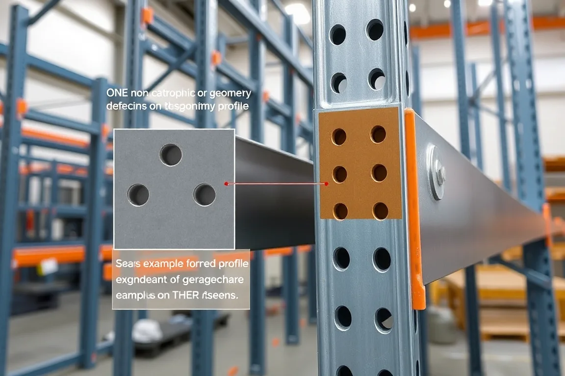
Troubleshooting a storage rack roll forming machine is not a matter of turning a dial until the defect disappears. Rack uprights, beams, and shelf components have to interface with connectors, mating geometry, and each other. A fault can originate in incoming strip, in the forming sequence, at the cutoff, during welding or assembly, or from handling after the line. The practical goal is to localise the defect to one stage, collect evidence that distinguishes it from nearby causes, and keep changes controlled. This page explains common defect symptoms, the diagnostic logic behind them, and how to compare alternatives such as in-line versus secondary operations. It does not provide hazardous intervention steps; adjustments to moving machinery belong to a qualified process under the equipment manufacturer's procedures.
Why troubleshooting differs from machine setup
Setup establishes a known starting point for a given profile, material grade, thickness, and finish sequence. Troubleshooting begins when output departs from that known-good condition. The distinction matters because a defect can come from a deliberate product change: a new coil lot, a different base-metal thickness, or a revised hole pattern. Treating a material-driven variation as a machine fault can lead to unnecessary tooling changes. Treating a tooling problem as material variation can allow a progressive dimensional drift to continue. A useful first question is whether the fault appeared after a coil change, a setup change, or gradually across a run. That question separates material and reference conditions from wear or thermal effects.
Storage rack components also include interfaces that a former alone does not control. A box beam may be assembled from more than one formed section. Connector attachment, welding, and rack-system approval sit outside the forming machine's scope. A troubleshooting method that only examines the formed section will miss joining and handling contributions. Documenting the defect with part identity, coil lot, drawing revision, and measurement conditions gives the evidence needed to decide where to look next.
Symptom patterns and what they suggest
Defects in rack roll forming tend to appear as dimensional drift, surface damage, hole quality problems, cutoff defects, or assembly misfit. Each pattern points toward different stages. Dimensional drift across consecutive pieces can suggest tooling wear, thermal growth, or strip property variation. Isolated surface marks may come from handling, coil edges, or contact with a guide. Hole quality problems, such as elongation or burrs, often relate to punching before forming, punch wear, or strip movement. Cutoff defects, including angle error or deformation, usually involve cutoff timing, blade condition, or support during cut. Assembly misfit, where a beam connector does not engage the upright consistently, may combine hole position, section straightness, and joining variation.
The key is to compare like with like. If you check one upright against one beam, you learn little. Check several consecutive pieces, then check after a material change. Use the same measurement method each time. A known-good reference part from the same drawing revision helps separate real drift from measurement noise. The existing editorial context for this topic makes a useful point: if connectors do not engage consistently, distinguish hole wear from section dimensional drift. That distinction determines whether the issue is in the punch station or in the forming stations that set the connector mating geometry.
Material and reference conditions to record
Material variation is a normal part of production, not an exception. Structural steel grades and thicknesses within an agreed range can behave differently through the same tooling. Post-forming finish sequence also matters: a component finished before or after forming can have different dimensional and surface outcomes. For troubleshooting, record the grade, thickness, and finish sequence for each component. Note the coil lot and any change in supplier or incoming condition. If the defect correlates with a coil lot change, the forming setup may be sound and the incoming strip may be the variable. If the defect persists across lots, tooling or setup is more likely.
Reference conditions include the strip width and edge condition, the lubricant or coating if used, and the line speed. These are not universal constants; they are conditions to record so that comparisons are meaningful. A shelf panel and a structural upright can need very different strip and tooling requirements. Upright sections often carry connector holes and returns; shelf panels may be simpler but still have flatness and handling needs. Do not assume that one troubleshooting result transfers from a shelf panel to an upright. The profile, the material, and the acceptance criteria differ.
Forming stage diagnostics without hazardous intervention
Forming defects include twist, bow, camber, oil-canning of flat areas, edge wave, and incorrect flange angles. These symptoms can arise from roll alignment, roll pressure, strip width, or material yield. You can observe output before cutoff where safely possible, but do not reach into running machinery or improvise adjustments around stored energy. A safer diagnostic approach is to stop the line under the equipment manufacturer's procedure, inspect the formed section at intermediate stations if the design allows, and compare with a known-good sample. Look for progressive changes along the line: a defect that appears after a certain pass points to that pass or the preceding material condition.
Because forming is a sequence, interfaces matter. Punching before forming can introduce holes that distort during subsequent passes. If hole position drifts while section dimensions remain stable, the punch station or strip tracking may be involved. If section dimensions drift while holes remain consistent, the forming rolls or material properties may be involved. This is why disturbance should be separated into forming, cutting, joining, and handling effects rather than treated as a single machine problem. A controlled change of one variable at a time, under the equipment manufacturer's procedure, is the only reliable way to confirm cause.
Cutoff and end-quality symptoms
Cutoff problems show up as length variation, burrs, deformation at the cut end, or angle error. The profile-supported cutoff needs to match the section. A cutoff designed for one profile may not support another, leading to end distortion. Confirm cut lengths and any secondary operations as part of the process definition. For troubleshooting, measure across several consecutive pieces to see whether length variation is random or trending. Random variation suggests cutoff timing or blade condition; a trend suggests thermal drift or material feed variation. End quality also affects downstream assembly, especially where cut ends mate with connectors or other components.
Cutoff is a stage where material handling and machine condition overlap. If the finished handled part shows damage that is not present before cutoff, handling after the line is the likely contributor. Keep a known-good reference and use the same measurement method for pre-cutoff and post-handling comparisons. This prevents attributing a handling mark to the forming rolls.
Joining, welding, and assembly effects
For built-up box beams, include the joining operation and its quality checks. A former does not automatically include welding, connector attachment, or rack-system approval. Troubleshooting that stops at the formed section can miss weld distortion, inconsistent connector attachment, or assembly fixture wear. If connector engagement is inconsistent, test beam connector engagement with the upright as an assembly check, not only as a formed-part check. Repeat the check across several pieces and after material changes. Distinguish hole wear from section dimensional drift by measuring hole position and section geometry on the same parts. If holes are within expectation but the connector still does not engage, the mating geometry or joining operation may be the source.
Assembly effects also include the sequence of operations. If a component is formed, then joined, then finished, each stage can introduce variation. Record the sequence and compare output before and after each stage where it is safe to do so. This is how you separate a forming defect from a joining defect. The acceptance approach for a rack component should reflect the actual interface, not just the formed profile.
Practical troubleshooting checklist
- Record the defect with part identity, coil lot, drawing revision, and measurement conditions.
- Confirm whether the fault started at a coil change, a setup change, or gradually during a run.
- Compare incoming material, output before cutoff where safely observable, and the finished handled part.
- Separate forming, cutting, joining, and handling effects before changing anything.
- Check several consecutive pieces and repeat after a material change.
- Keep a known-good reference part from the same drawing revision and use the same measurement method.
- Test beam connector engagement with the upright as an assembly-level check.
- For built-up box beams, include the joining operation and its quality checks.
- Change one controlled variable at a time under the equipment manufacturer's procedure.
- Escalate safety-related or qualified-process changes to the responsible engineer.
Comparing alternatives: in-line versus secondary operations
One tradeoff in rack component production is whether operations such as punching, cutoff, welding, or connector attachment happen in-line or in secondary steps. In-line operations can reduce handling and keep dimensions referenced to the same strip, but they also couple stages: a punch problem can affect forming, and a cutoff problem can affect downstream assembly. Secondary operations can isolate stages and allow inspection between them, but they add handling, which can introduce its own damage and dimensional variation. The right choice depends on the profile, the interface requirements, and the accepted output definition.
Another tradeoff is between a dedicated line and a flexible line. A dedicated line can be optimised for one upright or beam family, with tooling and cutoff matched to that profile. A flexible line may handle several profiles but can require more setup and changeover attention. Neither is inherently better; the decision depends on the product mix, the accepted output per shift with the actual profile and material, and the tolerance stack at the connector interface. For troubleshooting, a dedicated line gives a clearer known-good baseline, while a flexible line requires more rigorous recording of setup conditions.
Acceptance criteria that support troubleshooting
Acceptance criteria are only useful if they are measurable and tied to the interface. Relevant checks include beam connector engagement with the upright, repeated hole inspection, and section straightness. For built-up box beams, include the joining operation and its quality checks. Define accepted output per shift with the actual profile and material, not with a generic figure. This makes it possible to distinguish a normal material-driven variation from a genuine defect. Power requirements, voltage, frequency, and phase belong to the equipment schedule and should be confirmed separately; they are not troubleshooting variables in normal operation.
Because no verified model rating is assumed here, avoid using published output figures as a baseline. Instead, establish an internal accepted condition for the specific product and record it. Then compare current output against that condition. If the defect is outside the accepted condition, use the checklist to localise it. If it is inside, no corrective action is needed. This disciplined approach prevents unnecessary changes that can introduce new variation.
Frequently asked questions
Why do connectors fail to engage even when the upright looks correct?
Connector engagement depends on hole position, hole quality, section straightness, and the mating geometry of the connector. An upright can look correct in overall shape while hole position or local flatness is outside the interface requirement. Check repeated holes across several consecutive pieces, measure section straightness, and test engagement as an assembly. Distinguish hole wear from section dimensional drift by comparing hole measurements and section measurements on the same parts.
How can I tell whether a defect comes from material or from tooling?
Compare across coil lots and after material changes. If the defect correlates with a specific lot or grade, material is the likely variable. If it persists across lots under the same setup, tooling or setup is more likely. Record grade, thickness, and finish sequence for each component, and keep the measurement method consistent. A known-good reference part from the same drawing revision helps separate real drift from measurement noise.
What should I do if the defect appears only after cutoff?
If the formed section is acceptable before cutoff but the cut part is not, focus on cutoff support, blade condition, and handling. Measure length and end quality across several pieces to see whether variation is random or trending. Keep a known-good reference and compare pre-cutoff and post-handling parts. Do not reach into running machinery; inspect under the equipment manufacturer's procedure.
Why is it important to separate forming, cutting, joining, and handling?
Because each stage has different causes and different corrective actions. A handling mark looks similar to a forming mark until you compare stages. A joining distortion can mimic a forming defect. Separating effects prevents changing the wrong part of the process. It also supports a controlled change of one variable at a time, which is the only reliable way to confirm cause.
How do I set acceptance criteria for rack components?
Tie criteria to the actual interface: beam connector engagement with the upright, repeated hole inspection, and section straightness. For built-up box beams, include the joining operation and its quality checks. Define accepted output per shift with the actual profile and material, and record it as an internal baseline. Avoid generic figures that are not tied to your product.
What should I escalate rather than adjust myself?
Escalate safety-related or qualified-process changes to the responsible engineer. This includes adjustments to moving machinery, changes to stored energy systems, and changes that affect structural performance or connector engagement. Troubleshooting evidence gathering is appropriate; hazardous intervention is not. Keep records and pass them to the qualified process owner.
Continue your research
- Storage Rack & Shelving Roll Forming Machines
- Rack Upright Roll Forming Machine
- Pallet Rack Beam Roll Forming Machine
- Teardrop Rack Upright Roll Forming Machine
- Pallet Rack Box Beam Roll Forming Machine
- Pallet Rack Step Beam Roll Forming Machine
- How Storage rack roll forming machine Works
- How To Choose a Storage rack roll forming machine
- Storage rack roll forming machine Price: What Affects the Cost?