
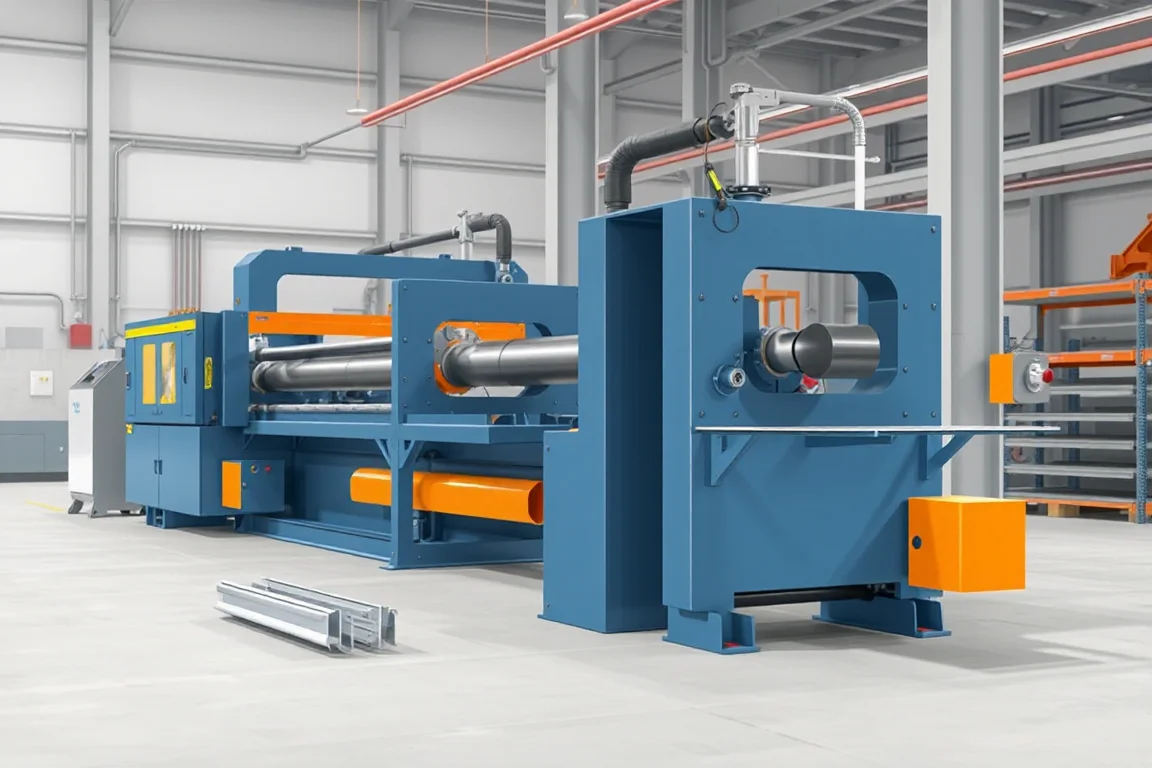
A rack upright roll forming machine produces the vertical profiles used in a specified storage-rack frame. The product combines a formed section with repeated connection features that locate beams, bracing and other components. Its functional accuracy depends on the relationship between the section and the perforation pattern, not on either one alone.
The equipment should follow the controlled upright design and its mating connectors. Similar-looking rack systems can use different hook openings, pitches and section geometry. A machine proposal is useful only when it identifies the exact family of uprights the factory intends to manufacture.
What defines an upright profile?
The section can include a front face, side walls, returns and stiffening geometry according to the rack design. The front features often provide the adjustable beam interface, while other faces can contain bracing or accessory connections. Each needs clear dimensional references.
Do not reduce the product to a nominal column width. Two uprights of the same outside width may have different connector seating surfaces or return geometry. Their tools, feature patterns and assembly checks should remain distinct.
Which drawings should control development?
- Complete upright section with bend radii and functional datums.
- Beam-connector opening shape, pitch and orientation.
- Bracing, base and accessory features.
- Material grade, thickness and finishing route.
- Length variants and end references.
- Intended beam connectors, braces and base components.
Provide mating components and an assembled reference where available. A connector drawing is especially useful because a small opening or seating difference can affect engagement even when the upright's broad dimensions appear correct.
How are perforation and forming coordinated?
The proposed route must place features correctly in the finished section. Punching on flat strip requires a controlled relationship to the subsequent bends, while later feature operations need suitable access and support. Ask the supplier to explain the actual sequence and datums.
Inspect opening position and geometry on completed uprights. Local distortion around perforations can influence the connector interface, so a flat-strip inspection alone is insufficient. Keep feature shape, burr condition and positional accuracy as separate checks.
Repeated pitch should be verified over several intervals and relative to the designated end. A pattern may repeat consistently yet begin at the wrong reference, producing an upright that does not align with the intended frame layout.
What does the production route include?
- Release the correct upright and feature configuration.
- Identify and guide the approved coil.
- Produce the required connection and accessory openings.
- Progressively form the front, sides and returns.
- Cut the required length with suitable section support.
- Inspect, mark and group accepted uprights for frame assembly or finishing.
Where the factory supplies completed frames, bracing and base attachment require additional operations. Define those separately rather than treating the upright former as a complete rack-frame line by itself.
How should grade and thickness be specified?
List actual grade, thickness, strip width and finish combinations for each upright. Different load-design families may use similar external shapes with different material requirements. The production and identification system must keep those components distinct.
Use representative material in trials and retain its identity with sample measurements. Forming response and local feature condition can change with the stock, so a successful demonstration on one material does not establish every catalogue combination.
Final rack capacity is not determined by the former's material range. It depends on the complete rack design, connections, configuration and relevant verification. The machine trial should establish accurate manufacture of the approved upright, not invent a load rating.
How should beam-connector fit be checked?
Use the intended connector and assembly method on production-length uprights. Check engagement at several feature positions, including near the ends where applicable. Inspect seating surfaces and the condition of the opening after assembly.
Record tightness, looseness, incomplete seating or the need for local modification. A connector that can be forced into one selected opening is not a reliable pass. Dimensional measurements should accompany the fit observations so the source of a deviation can be identified.
Any locking or retention component belongs in the trial where specified. Mechanical fit does not replace the connection's required performance verification, but omitting the real hardware leaves manufacturing compatibility unresolved.
What changes between upright sizes?
Separate section width, depth, return geometry, material and hole-pattern changes. A line may adjust some dimensions while requiring tools for others. Ask for a matrix of rolls, guides, punches, cutoff parts and settings for each configuration.
Demonstrate a meaningful transition and return to the original upright. Include feature inspection and connector fit in first-good-product timing. A rapid mechanical adjustment is only useful when accepted output can be recovered repeatably.
If several connector families are planned, treat their openings as separate controlled products. Similar pitch or appearance does not justify using one tool pattern for another rack system without the relevant design review.
Why are straightness and twist important to frame assembly?
Long uprights must align with bracing, bases and beams under the intended assembly conditions. Inspect them using defined supports and measurement references. Distinguish persistent twist from local end distortion or a handling-related bend.
Where frames are welded or otherwise assembled after forming, compare component and completed-frame measurements. A deviation introduced during joining should not automatically be corrected by changing the upright roll tools.
Retain setup sheets and reference parts. They give production staff a concrete baseline when a later batch becomes difficult to assemble rather than relying on visual memory.
What secondary operations and finishing need scope?
Bracing attachment, base plates, splices and other features may involve separate joining or fabrication. Identify the required equipment and fixtures if complete frames are part of the project. The component former should not be credited with work performed elsewhere.
Define the finishing route and inspect the final condition of connector openings and mating surfaces. Coating and handling can influence fit, so a raw formed sample is not always the final acceptance object.
Maintain identification through finishing. Similar upright sizes and thicknesses should not become mixed when they share a color or return from a subcontracted process.
How should handling and output be evaluated?
Provide a supported discharge path for the full length range and a bundle method that protects section and openings. Inspect representative parts after normal movement. Labels should identify section, material, pattern, length and production reference.
Measure accepted uprights for a stated order with all feature operations active. Punching, cutoff, changes and collection can set the practical cycle. If complete frames are supplied, include the assembly and finishing stages in the overall capacity study.
For planning only, 300 frames containing two uprights require 600 accepted uprights, plus their specified bracing and bases. That count does not establish a rack layout or load rating; it illustrates why component balance matters to finished-frame output.
What should quotation and acceptance cover?
Compare the same upright and material matrix, including feature tools, forming configurations, cutoff, handling and inspection aids. Identify frame assembly, finishing and product qualification separately. Future connector families should have explicit tooling assumptions.
- Verify section and finished opening geometry.
- Measure pitch and end-referenced feature positions.
- Check length, ends, straightness and twist.
- Assemble intended beam connectors and frame interfaces.
- Demonstrate required changes and setup recovery.
- Inspect final finish, identification and bundle condition.
- Record accepted quantities and unresolved deviations.
Keep the trial's material, drawings, hardware and setup references together. A complete reference set supports repeat production more effectively than an isolated profile sample.
Frequently asked questions
Can one upright accept every rack beam connector?
No. Opening shape, pitch and seating geometry differ between systems. Use the intended connector during development and acceptance rather than assuming compatibility from nominal column width.
Does the machine make completed rack frames?
Only if bracing, bases, joining and required finishing are included. An upright former produces one component route. Define the complete-frame scope explicitly before comparing equipment packages.
Can hole pitch change through software?
Only within the installed punching and control capability. Different shapes or feature combinations can require tools. Supply every required pattern and demonstrate the commercially relevant transitions.
Why inspect after coating?
The delivered connector interface must work in its final condition. Finishing and handling can affect openings or fit. Coordinate raw-component checks with the required final assembly inspection.
Does accurate forming establish rack capacity?
No. Capacity belongs to the complete engineered rack arrangement and its relevant evidence. Machine acceptance establishes conformity of the specified component, not a universal load rating.
What should an enquiry include?
Provide upright and connector drawings, material combinations, feature patterns, lengths and frame-assembly scope. Add finishing, order mix and handling requirements. This gives the line a clear production target.

Continue your research
- Storage Rack & Shelving Roll Forming Machines
- Pallet Rack Beam Roll Forming Machine
- Shelf Panel Roll Forming Machine
- Teardrop Rack Upright Roll Forming Machine
- Pallet Rack Box Beam Roll Forming Machine
- Pallet Rack Step Beam Roll Forming Machine
- How Storage rack roll forming machine Works
- How To Choose a Storage rack roll forming machine
- Storage rack roll forming machine Price: What Affects the Cost?
Configuration & specification inputs
Match the configuration to your section drawing, material and production requirements.
| Parameter | Requirement / confirmation needed |
|---|---|
| Profile geometry | Upright front, sides and returns linked to beam and bracing interfaces |
| Material | Specified rack-component grade and finish with retained coil identity |
| Thickness & grade | Approved grade/thickness/section combinations kept distinct through finishing |
| Process route | Controlled openings, upright forming, cutoff, identification and separately scoped frame assembly |
| Cutting | Maintain end-referenced feature positions and avoid local connector-interface distortion |
| Output | Accepted patterned uprights or completed frames according to the stated boundary |
| Electrical supply | Confirm utilities for punching, forming, cutting, handling and included assembly |
| Acceptance | Measure section and repeated features, use intended beam connectors and verify final finished fit |