
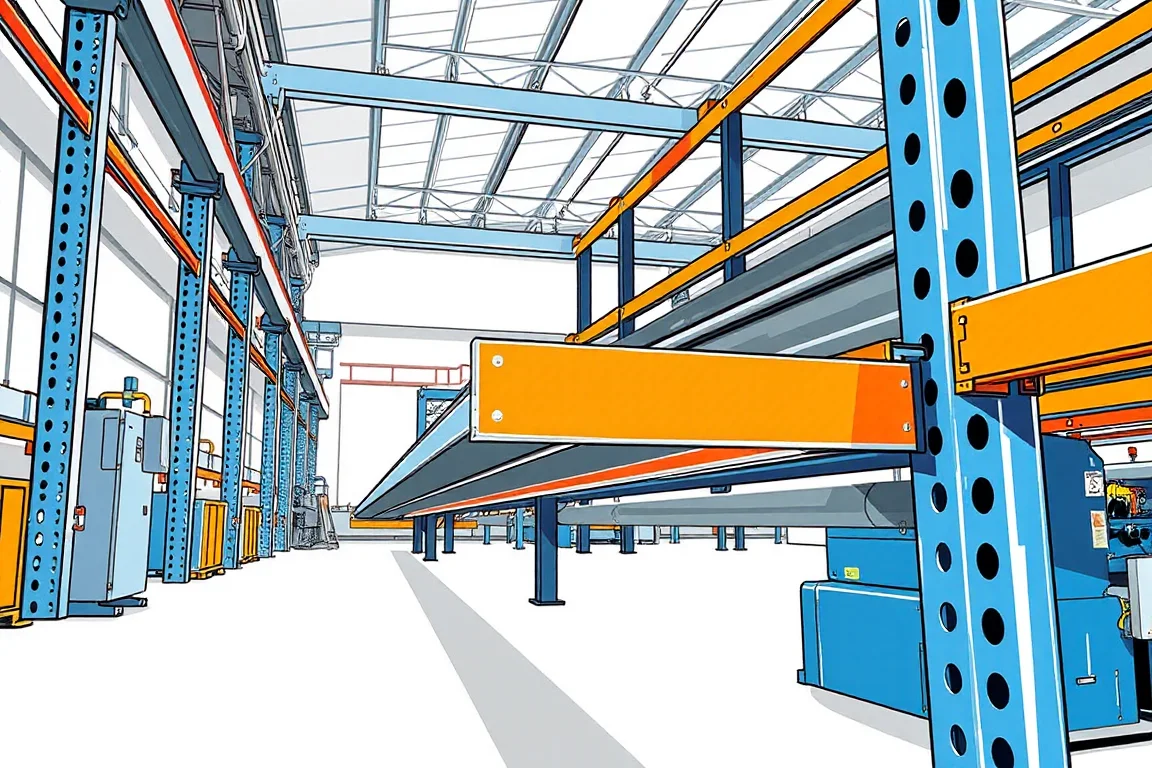
A pallet rack step beam is not a simple channel. It is a structural member that carries pallet loads and presents an internal ledge, or step, on which decking, wire mesh or shelf panels rest. The step beam roll forming machine must produce that bearing surface to a defined geometry so supported components sit correctly and the beam connector engages the upright as intended. This page explains how a step beam differs from nearby rack components, how production routes are assembled, and what to inspect before accepting a line.
What a Step Beam Does in a Rack Structure
A step beam spans between upright frames and transfers load into the frame connectors. The step ledge runs along the beam and supports decking or shelf panels. The connector at each end transfers load into the upright's slot pattern. Because the step is a functional bearing surface, its position, width, angle and edge condition matter as much as the outer profile height. A beam that looks correct on the outside can still fail seating checks when the connector geometry, the ledger depth or the step return is wrong.
Interfaces That Define the Component
Three interfaces govern the drawing:
- Connector-to-upright: the beam end connector must engage the upright's slot pattern with the intended bearing contact.
- Step-to-decking: the step ledge and its return must accept the panel or decking without rocking or overhang.
- Beam-to-beam or beam-to-frame: any joining, bolting or welded bracket that positions the beam relative to the frame.
These interfaces are often more critical than an overall channel width. If the connector does not engage, the rack cannot be assembled even if the formed section measures correctly.
Production Route: Punching, Forming, Cutoff, Welding
The typical route is punching, section forming, cutoff, then welding or assembly where required, followed by inspection. Some step beams are formed from a single strip; others are built up from two or more formed sections welded into a box or composite beam. Each route places different demands on the line.
Punching should be defined by hole type, pattern and datum. In a step beam, connector holes and any decking-retention holes may be punched before forming or after, depending on the tooling strategy. Pre-punching is common for connector patterns that must be positioned relative to the beam end; post-forming punching can be used for features that are easier to place after the section is closed. The choice affects scrap, tool access and the repeatability of hole position after forming springback.
Why the Step Ledge Is Not Just a Formed Feature
The step is the part of the beam that touches the load. Its flatness, the radius or return at the inner edge, and the stability of the step under load all affect how decking sits. A step that is under-formed or over-formed can leave a gap between panel and beam, concentrate load on an edge, or prevent the panel from seating. For this reason, inspection should measure the step relative to the connector and to the beam's outer datum, not only section height and width.
Single-Section Beams and Built-Up Box Beams
Step beams are produced in two broad configurations. A single-section beam is roll formed from one strip with the step integrated into the section. A built-up beam is assembled from formed sections, often welded, to create a closed or composite profile with greater stiffness. The roll forming machine scope differs accordingly.
For a single-section beam, the line may include punching, forming, cutoff and end processing. For a built-up beam, the line usually includes forming of each section, then a separate joining operation such as welding, plus inspection of the joint. Joining can change the seating geometry if heat or clamping distorts the section, so the accepted part must be checked after joining rather than only as a bare roll-formed sample.
Cutoff Requirements and End Quality
Cutoff must suit the profile and the end condition. Some step beams require square ends for connector attachment; others require formed or punched end features. The cutoff die should support the section internally where needed to avoid collapsing or twisting the step. Cut length, end squareness and burr condition should be defined on the component drawing. If secondary operations such as end notching or hole drilling occur after cutoff, they belong in the equipment scope and in the acceptance sample.
Assembly Boundaries: What the Line Does and Does Not Do
A forming machine does not necessarily produce a finished rack beam. A complete production route may include:
- Decoiling and strip feeding
- Punching of connector and feature holes
- Roll forming of the section and step
- Cutoff to length
- Welding or mechanical joining of built-up sections
- Installation or attachment of end connectors
- Finishing such as painting or coating, if specified
- Final inspection
The equipment scope must be compared against the operations actually needed for a finished part. A bare forming mill is not equivalent to a complete step beam line, and a quotation based only on the mill may omit welding, connector assembly or handling that the product requires.
Inspection and Acceptance for a Finished Step Beam
Acceptance should verify the agreed component drawing and the intended interfaces. Practical checks include:
- Test beam connector engagement with the upright, using the actual upright and connector.
- Inspect repeated hole positions against the datum, including after forming.
- Measure section straightness and step ledge geometry relative to the connector.
- Inspect the step bearing surface for flatness, edge condition and correct return.
- For built-up beams, check the joining operation and its quality before final acceptance.
- Confirm that joining and finishing have not changed the required seating geometry.
Where decking is part of the system, seat the intended panel or shelf on the step and check that it rests without rocking or edge loading. Compare completed beams rather than approving only an unjoined roll-formed sample.
Choosing Between Alternative Production Routes
Route choices include pre-punch versus post-punch, single-section versus built-up beam, and inline cutoff versus secondary cutting. Pre-punch suits high hole density and connector patterns that must be located before forming; post-punch can be simpler for low hole counts or features that need access to the closed section. Single-section forming reduces joining steps but may limit stiffness or step geometry. Built-up beams allow greater section depth or closed profiles but add welding and distortion control. Inline cutoff supports continuous production; secondary cutting can allow different end treatments with simpler tooling. None of these is universally better; the right route follows the component drawing, material and batch structure.
Material and Thickness Inputs
The step beam drawing should define the base-metal grade, thickness and the finish sequence. A specified structural steel with an agreed post-forming finish is typical. The operating range of thickness and grade requires supplier verification, because tooling and forming loads change with material strength and thickness. A shelf panel and a structural upright can need very different strip and tooling requirements, so the step beam should be evaluated as its own product rather than as a variant of an upright line.
Defining Output Without Invented Ratings
Output should be defined as accepted parts per shift with the actual profile and material, after all included operations. Punch density, welded assemblies and batch sizes affect throughput. Measure accepted beams after welding, connector attachment and any finishing, not only at the forming mill exit. Compare punch tooling, roll tools, welding or assembly scope and automatic handling separately when evaluating proposals.
FAQ
What makes a step beam different from a box beam?
A step beam has an internal ledge that supports decking or shelf panels. A box beam is typically a closed rectangular section that may not include a shelf-supporting step. The connector and upright interfaces are similar in principle, but the step geometry and its inspection requirements are specific to the step beam.
Can a step beam roll forming machine also produce uprights?
Sometimes a line is configured for multiple profiles, but the upright and the step beam have different section shapes, hole patterns and tooling needs. A machine set up for a step beam should be evaluated on that component drawing, not assumed to cover upright production without a demonstrated tool change.
Should punching happen before or after forming?
Punching before forming is common when holes must be positioned relative to the beam end or connector pattern. Punching after forming can suit features that are easier to access on the closed section. The decision depends on hole type, datum, tool access and how forming springback affects hole position.
How should a built-up step beam be inspected?
Inspect the joining operation and the finished beam. Welding or mechanical joining can distort the step or connector seating, so the accepted part should be checked after joining. Confirm that the step ledge and connector still match the drawing and that the intended decking seats correctly.
What should be included in the equipment scope?
The scope should list every operation needed for a finished beam: punching, forming, cutoff, welding or joining, connector attachment, finishing if specified, and handling. Compare that written scope with the component drawing before approving the line.
How is output evaluated for a step beam line?
Output is evaluated as accepted beams per shift with the actual material and profile, including all secondary operations. Punch density, welding and batch changes affect throughput, so the measurement should be taken after the last operation that defines the finished component.
Practical Checklist Before Approving a Line
- Confirm the component drawing defines connector, step and decking interfaces.
- Record grade, thickness and finish sequence for the beam.
- Define each hole type and its datum.
- Confirm cutoff supports the step and end quality requirements.
- Include welding, joining or connector attachment in the scope.
- Run the agreed material and profile, not an easier substitute.
- Inspect first-off and steady-production samples with agreed gauges.
- Test connector engagement with the upright and seat the intended decking.
- Record changeover steps, setup scrap and unloading time.
- Compare completed beams rather than only the forming mill output.
Rack load capacity is established for the finished racking design, not from the forming machine alone. The step beam line should be judged on whether it reliably produces components that assemble and function in that design.

Continue your research
- Storage Rack & Shelving Roll Forming Machines
- Rack Upright Roll Forming Machine
- Pallet Rack Beam Roll Forming Machine
- Teardrop Rack Upright Roll Forming Machine
- Pallet Rack Box Beam Roll Forming Machine
- Slotted Angle Roll Forming Machine
- How Storage rack roll forming machine Works
- How To Choose a Storage rack roll forming machine
- Storage rack roll forming machine Price: What Affects the Cost?
Configuration & specification inputs
Match the configuration to your section drawing, material and production requirements.
| Parameter | Requirement / confirmation needed |
|---|---|
| Profile geometry | A step beam includes a ledge that supports decking or shelves. Inspect that functional bearing surface and its relationship to the beam connectors, not only the outside section dimensions. |
| Material | Specified structural steel with an agreed post-forming finish |
| Thickness & grade | Buyer to specify base-metal thickness and grade; operating range requires supplier verification. |
| Process route | Punching → section forming → cutoff → welding/assembly where required → inspection |
| Cutting | Confirm profile-supported cutoff, cut lengths, end quality and any secondary operations. |
| Output | Define accepted output per shift with the actual profile and material. |
| Electrical supply | Buyer to state voltage / frequency / phase. Installed power requires a confirmed equipment schedule. |
| Acceptance | Inspect a finished beam with the intended supported component. Confirm that joining and finishing have not changed the required seating geometry. Compare completed beams rather than approving only an unjoined roll-formed sample. |