
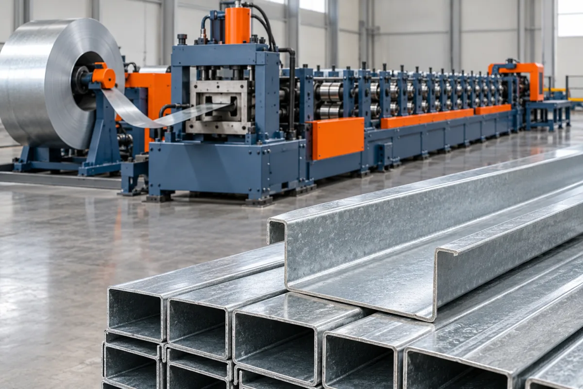
A U purlin roll forming machine produces an open channel used as the specified member in a roof or wall support system. The name usually describes a web with two flanges, but it does not establish whether the edges are plain, returned or otherwise modified. The actual section drawing must define the product before a machine configuration is selected.
A U profile should not be treated as a C purlin with an unspecified feature omitted. Removing or changing lips alters the manufactured section and may change its application. The equipment brief should follow the approved member geometry and connection details rather than an informal letter shape.
What should the U-section drawing contain?
Define web width or depth using clear datums, both flange dimensions, bend radii and edge condition. Show whether the flanges are parallel, inclined or have any returns. Include the material and the surfaces used for connection features.
Where the term U purlin is used locally for a special support member, provide a physical reference and its intended assembly. A generic channel sketch may miss the feature that distinguishes that product from ordinary fabricated U channel.
How does it differ from lipped C purlin?
A conventional lipped C section includes returns at the flange ends, while a plain U channel does not. The difference affects tooling development, cut support and the final member geometry. It also means that structural properties cannot be transferred from one section to the other by name.
If both products are required, request a tooling review and variant schedule. The proposal should explain which rolls, guides and cutting parts change. Do not assume the lip-forming stages can simply be ignored without affecting the remaining section.
Which connection features need to be specified?
List web and flange holes, slots, notches and end details. Define their positions from the finished member and cut ends. Include mating cleats, brackets or other references where they determine practical fit.
- Hole or slot shape and size.
- Longitudinal pattern and end distance.
- Transverse datum on the web or flange.
- Required unpunched zones.
- Connection orientation and member identity.
A blank U sample is not enough to approve a line intended for feature-rich structural orders. The actual punching schedule should be part of the production trial.
How is the channel manufactured?
Coil support and entry preparation feed the strip into the agreed punching and forming route. Progressive rolls develop the web-to-flange bends and any specified edge detail. The cutting system then produces lengths for supported discharge and identification.
Review the actual order of operations. Pre-punching, post-forming features and different cutting arrangements can have different equipment and cycle implications. The proposed sequence should be demonstrated with the real section and feature pattern.
How should material and size ranges be described?
Use a matrix pairing grade, base-metal thickness and strip width with each target channel. A broad web range does not imply every flange and material combination is covered. Include coating and incoming-strip requirements.
For variable sizes, distinguish dimensions adjusted within one tool family from those requiring new parts. The matrix should include the first-good-member checks after each relevant change. This turns an adjustable-channel claim into a testable production scope.
What shape deviations deserve attention?
Check flange angle, opening width, straightness and twist using agreed supports. A plain channel's open edges should be measured without forcing them into a fixture that hides deviation. Inspect both ends and an interior section.
Local end flare or closing can come from the cutting and transfer process even when the central section is acceptable. Record that separately from general bend geometry. The distinction helps identify whether the issue concerns forming, cutoff support or handling.
How should discharge and bundles be arranged?
Define the length range and normal bundle format. Channels may nest, but the stack arrangement should not distort flanges or obscure product identification. Review the shortest pieces as well as the longest members.
For mixed sizes, agree labels and bundle separation. A U member can look similar to another size while having different hole positions or material. Traceability to the order and drawing is a practical part of delivering the correct product.
What should a complete trial demonstrate?
- Verify section drawing, material and feature program.
- Measure web, flanges, angles and opening.
- Check holes against connection and end datums.
- Inspect straightness, twist and cut-end condition.
- Fit representative mating components.
- Demonstrate required size changes and normal stacking.
- Record accepted members and startup waste.
Use accepted orders as the production measure. Punching density, short lengths and bundle handling can be more important than steady forming speed in a practical U-channel operation.
Frequently asked questions
Is U purlin always a plain channel?
Not in every naming convention. Confirm the actual edges, flange angles and intended assembly. The controlled drawing should take precedence over the product nickname.
Can C purlin tooling make it without changes?
That requires review. Lip removal or different flange geometry can affect the forming sequence and cutoff. Ask for the specific tooling arrangement for the approved U section.
Does the machine determine the member's span?
No. Structural suitability comes from the member and system design. The equipment should manufacture the specified geometry and material accurately.
Why check the opening without clamping?
Forcing the flanges into position can hide the delivered shape. Use the agreed relaxed inspection condition so measurements represent the member customers receive.
What information starts a useful quotation?
Send section drawings, material combinations, feature patterns, lengths and order mix. Include mating references and any C or other profile also required so shared-tooling scope can be assessed.
Define the channel beyond its letter shape
A U-purlin line should be selected for the actual open section, connections and production schedule. Clear geometry and relaxed-part acceptance make the proposal more useful than a generic channel-machine description.

Continue your research
- Purlin Roll Forming Machines
- C Purlin Roll Forming Machine
- Z Purlin Roll Forming Machine
- 80-300mm CZ Purlin Roll Forming Machine
- 100-400mm CZ Purlin Roll Forming Machine
- Automatic Size Change CZ Purlin Machine
- How Purlin roll forming machine Works
- How To Choose a Purlin roll forming machine
- Purlin roll forming machine Price: What Affects the Cost?
Configuration & specification inputs
Match the configuration to your section drawing, material and production requirements.
| Parameter | Requirement / confirmation needed |
|---|---|
| Profile geometry | Drawing-controlled U web, flanges, angles and plain or specified returned edges. |
| Material | Specified steel grade and coating for the intended support-member system. |
| Thickness & grade | Approved material-thickness and strip-width combinations for each U section. |
| Process route | Coil preparation, defined feature sequence, U forming, cutting and identified takeoff. |
| Cutting | Required lengths with controlled opening, flare and hole-to-end relationships. |
| Output | Accepted U-member orders including feature cycles, size changes and bundle preparation. |
| Electrical supply | Utilities matched to coil handling, punching, forming, cutting and discharge. |
| Acceptance | Relaxed opening, web and flange geometry, straightness, twist, holes and mating-component fit. |