
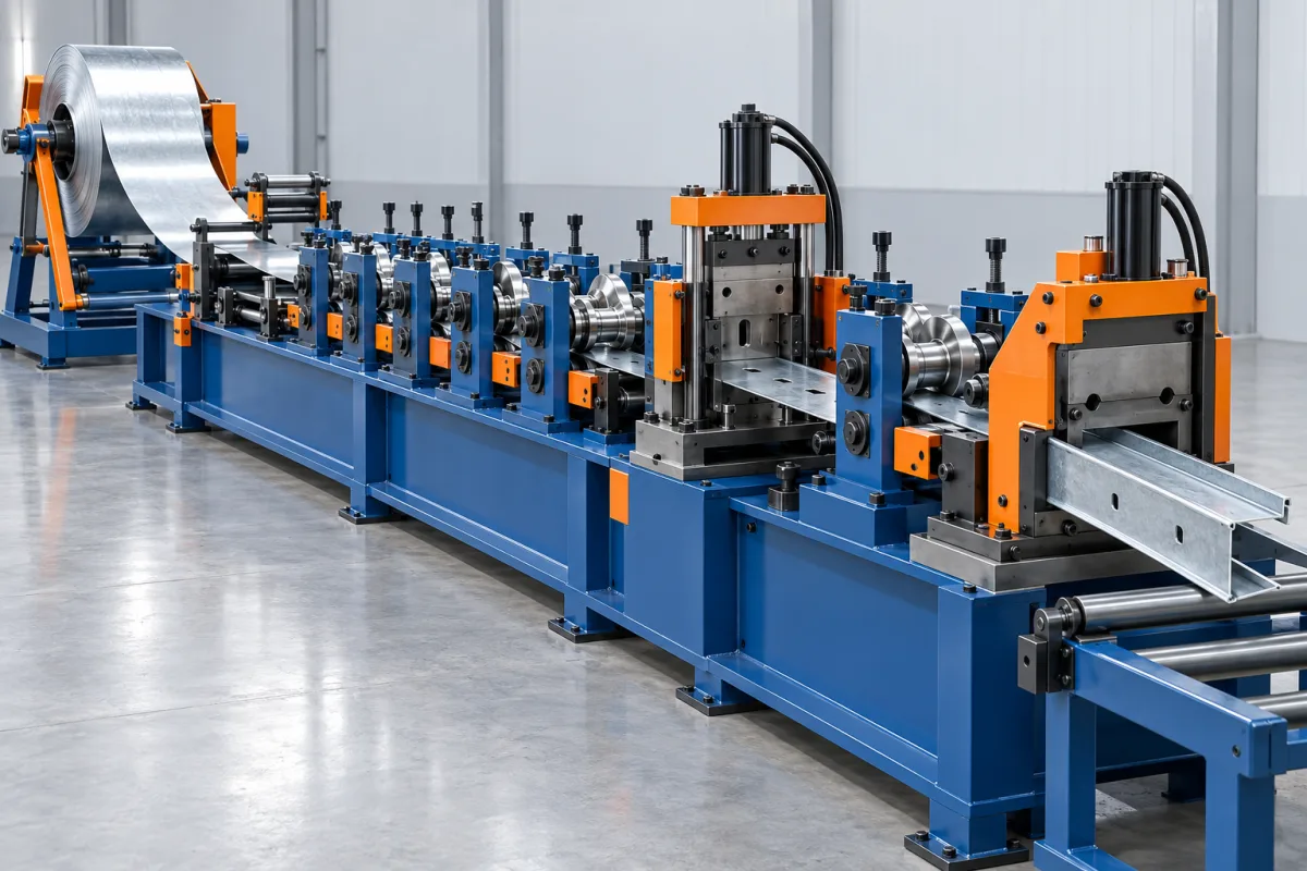
A purlin roll forming line converts coil into structural sections with the geometry, holes and identification required by a building order. The output is more than a C or Z silhouette. Webs, flanges, lips, connection features and cut length must agree with the engineered component drawing.
Start with the member and its connections
The production drawing should show the cross-section and the longitudinal hole or notch pattern. Identify datums used for each feature. Web height alone does not define the product, and a section without its connection details may be incomplete for the intended building package.
Keep structural design separate from equipment capability. The line makes the specified member; it does not establish the building's load capacity by virtue of forming a particular shape. Material, member geometry, connections and the structural system need their own approved design basis.
Coil preparation establishes the incoming condition
Payoff and the specified preparation equipment present the strip to the route. The enquiry should state coil dimensions, grade, thickness and width as combinations. A machine's nominal thickness range without a material-strength context is an incomplete capability description.
Record incoming material identity with the production order. If a later member shows a shape or hole problem, the team needs to distinguish a material change from a setup change. Traceability is practical troubleshooting information, not merely administrative paperwork.
Feature-making creates the connection pattern
Punching or notching can be integrated at a defined stage or assigned to another operation. The proposal should explain the chosen sequence and supported feature locations. Do not assume that every hole visible on the drawing can be reached by a standard punch arrangement.
Specify hole shape, size, location and orientation using the final member's references. A hole can be cleanly made but still unusable if it is located from the wrong end or on the wrong face. Feature inspection must therefore connect the production sequence to the finished part drawing.
Progressive forming develops web, flanges and lips
Successive stages develop the section from flat strip. The relationship among web, flanges and lips matters to the finished geometry. Ask how the proposed tooling covers the actual size and material combinations rather than judging the line by stand count.
C and Z sections have different flange orientations. A combination line needs a defined method for changing between them. That ability should not be confused with unlimited size flexibility: flange widths, lips and other features may still have specific boundaries.
Size change and C-to-Z conversion are separate questions
A proposal may automate some movements while retaining manual change parts or checks. Request the complete transition sequence. Identify guides, punch positions, forming adjustments, cutoff components and first-off inspection requirements.
Time the change through to an accepted member with the correct holes and end condition. A fast movement of the forming assembly is only part of the task. Returning to a previous size provides useful evidence that the setup references support repeatable production.
Cutting delivers the member and affects its ends
The line's cutting arrangement must be evaluated with the actual section and lengths. Precut and postcut concepts place the operation at different points in the route. Ask how the proposed design controls the finished ends and supports the required product range.
Inspect end flare, local distortion and length separately from the central cross-section. A good middle coupon cannot prove that the complete member connects correctly at its ends. Keep the inspection condition and datums consistent across the trial.
Discharge preserves straightness and order identity
Long purlins need a supported route into stacking and handling. The layout should accommodate the longest agreed member and the way bundles leave the line. If a formed component is bent during takeoff, the upstream process has not delivered an accepted product.
Identification is especially important when similar sections carry different hole patterns or lengths. Define how the order, member mark and material remain associated with the part. A correctly formed but wrongly identified member can cause assembly delays just as a dimensional defect can.
Count completed members rather than unloaded speed
Punch density, length mix and size changes affect output. A run with few features may not represent a building order containing many holes and short members. Use a representative part basket and count accepted completed components over a stated time boundary.
For a hypothetical basket of 40 members at 6 metres and 30 at 4 metres, accepted linear output is 360 metres if every member passes. The time study should retain both groups and their feature patterns; a single average length hides their different work content.
Follow one building order through acceptance
For an eave member or another additional section, use its own drawing and connection details. Its inclusion in a combination machine's catalog does not mean it follows the identical setup as a standard C purlin. The process review should identify that difference before the order reaches production.
A useful trial starts with controlled drawings and material, then checks the entire member. Include a meaningful size or orientation change and the intended feature operations. Record accepted quantity, scrap and unresolved deviations.
- Verify material and member drawing revisions.
- Measure web, flanges, lips and overall length.
- Check holes and notches from the specified datums.
- Inspect straightness and both ends under agreed support.
- Confirm member identification and bundle assignment.
- Repeat required checks after a configuration change.
Frequently asked purlin process questions
Does a CZ line make every C and Z section?
No. It has a defined geometry and material envelope. Obtain the supported size combinations and required change parts rather than treating CZ as a universal capability.
Are holes always punched before forming?
The sequence depends on the proposed route and features. Ask where each operation occurs and how the final member's feature positions are verified.
Does an accurate purlin prove its structural capacity?
No. Manufacturing accuracy is one requirement within the engineered building system. Structural capacity depends on the specified material, geometry, connections and design conditions.
What is the most useful trial part?
One representing a real order's section, material, length and connection pattern, accompanied by the appropriate boundary products. A plain section without holes may omit the operation that controls your production performance.
Continue your research
- Purlin Roll Forming Machines
- C Purlin Roll Forming Machine
- Z Purlin Roll Forming Machine
- 80-300mm CZ Purlin Roll Forming Machine
- 100-400mm CZ Purlin Roll Forming Machine
- Automatic Size Change CZ Purlin Machine
- How To Choose a Purlin roll forming machine
- Purlin roll forming machine Price: What Affects the Cost?
- Materials and Thickness for Purlin roll forming machine