
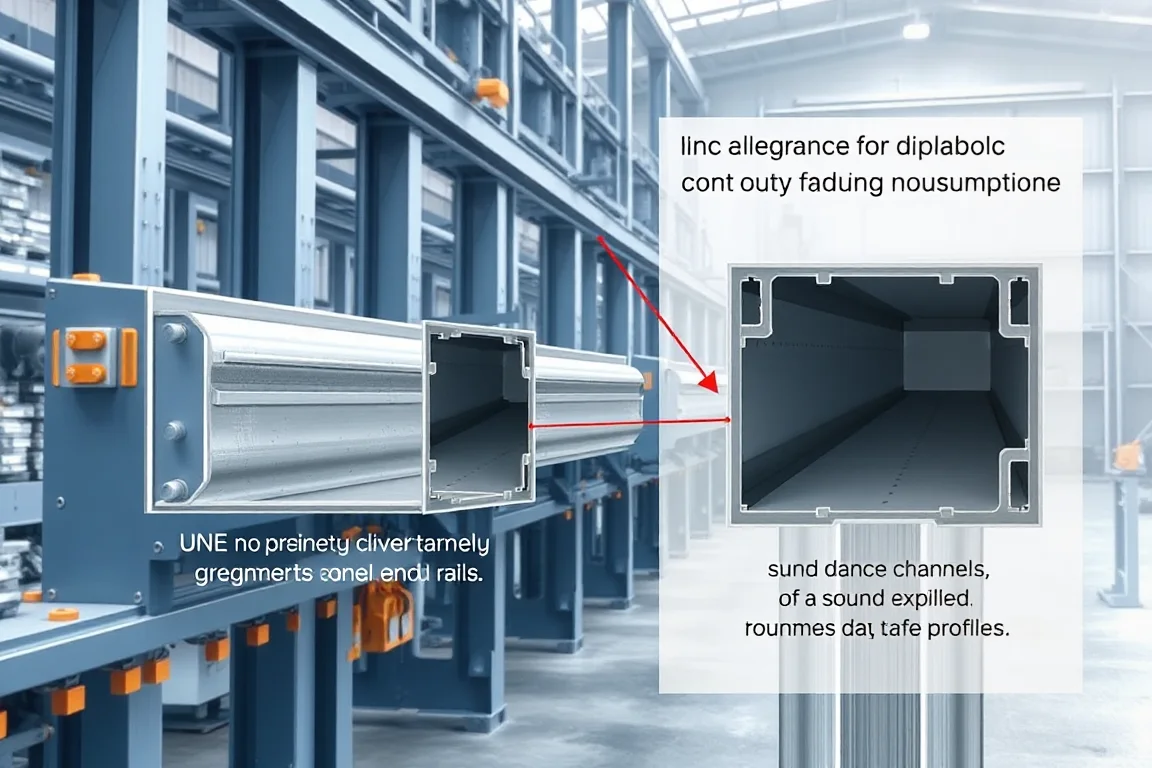
When a solar mounting rail or post leaves a roll forming line with a defect, the machine is not automatically the cause. The rail is the product of a chain: incoming coil, leveling, connection punching, channel forming, cutoff and handling. A fault that appears at the finished part can originate anywhere in that chain. Troubleshooting a solar roll forming machine is therefore a process of localizing the defect to a stage, then gathering evidence before any adjustment. The sections below explain how the process is structured, what different defects usually indicate, how to compare alternatives, and how to document a fault so that the responsible engineer can act.
What the forming sequence does and where defects enter
A typical solar rail line runs leveling, then connection punching, then channel forming, then cutoff. Each stage has an interface with the next. Leveling sets the flatness and residual stress state of the strip before it enters the forming stands. If leveling is inconsistent, the forming stands inherit a varying input and the resulting section can twist or bow. Connection punching creates holes, slots or notches that later receive clamps, bolts or brackets. If punch position drifts relative to the strip edge, the finished rail may meet its width specification while still rejecting the mating hardware. Channel forming bends the strip progressively into the rail or post section. Cutoff separates the finished length. The interfaces matter because an error introduced upstream can be amplified downstream, while an error at cutoff is usually confined to the end condition.
Symptoms that point to coil or material variation
Defects that begin at a coil change often show a step rather than a gradual drift. If the first good part of a run is acceptable and later parts in the same coil show increasing bow, twist or springback, the material may vary in thickness, yield strength or coating condition along the coil. Coating condition matters because it affects friction between the strip and the forming rolls, which in turn affects how much the strip slips or stretches. A useful diagnostic is to compare parts made from the same coil before and after a known event, such as a splice or a coil change. If the defect appears only after the event, the coil is the first area to examine. Material thickness alone does not establish outdoor durability, and coating selection depends on the installation environment.
Section defects: bow, twist, camber and springback
Bow is a curvature in the vertical plane along the length of the rail. Twist is a rotation about the longitudinal axis, so the flanges no longer sit in the intended orientation. Camber is a curvature in the horizontal plane. Springback is the elastic recovery of the strip after it leaves a forming stand. These defects can share a cause but have different signatures. Bow often relates to uneven roll pressure or a leveling condition that differs across the strip width. Twist can follow from asymmetric forming, worn or misaligned rolls, or a strip that enters the first forming stand at an angle. Camber can reflect a lateral offset in the line or a difference in edge condition. Springback depends on material grade and thickness, and it interacts with the tooling design. Because these defects can be caused by setup, tooling or material, the diagnostic evidence should include where in the line the defect first becomes measurable, not just where it is finally visible.
Cutoff and end-condition faults
Cutoff faults are often easier to localize because they occur at a known point in the sequence. A burr, a deformed end, a length that drifts, or a cut face that is not square usually points to the cutoff station or to the way the profile is supported as it is cut. If the section is not fully supported during cutoff, the cut can distort the end even if the forming stages produced a good section. The cut length can drift if the measuring device or the feed system is inconsistent, or if the material is slipping. End condition also affects downstream assembly, because a deformed end may not fit a splice or bracket. The practical check is to compare the cut end with a known-good reference and to note whether the fault changes with length, speed or material lot. Cut-length drift that appears only at certain lengths can indicate a feed or synchronization issue rather than a cutoff tool issue.
Hole and slot position faults
Connection punching creates the features that mounting hardware depends on. A slot that is offset along the rail, a hole that is not centered on the intended datum, or a pattern that is inconsistent from part to part will cause clamp fit problems even when the rail section itself looks correct. The key diagnostic is to measure the position of the feature relative to a stable datum on the finished part, not relative to the strip edge alone. If the feature position drifts progressively along the coil, the punching station or the feed system may be losing synchronization. If the feature is consistently offset but repeatable, the issue may be a setup or tooling datum. Because the clamp or bracket is the mating part, the actual hardware should be used as a gauge wherever possible. A rail that rejects a clamp may have a lip or slot error even if its overall width is correct.
Surface and coating damage
Coated structural steel is common in solar mounting, and surface damage can be a functional concern as well as a cosmetic one. Scratches, coating pickup on rolls, or burnished areas can indicate excessive roll pressure, contaminated rolls, or a handling problem after cutoff. The location of the damage is informative. Damage only on one side can point to a single roll or guide. Damage that appears at the same position on every part suggests a fixed interference. Coating damage that occurs after the forming line may come from conveyance, stacking or secondary handling. Because coating selection and damaged-edge treatment depend on the installation environment, the decision about whether a damaged area needs repair should be made with the coatings and installation requirements in view, not by appearance alone.
Diagnostic evidence to collect before any change
Effective troubleshooting depends on evidence that can be compared over time. Document the defect with part identity, coil lot, drawing revision and measurement conditions. Note whether the fault started at a coil change, a setup change, a tooling change or a maintenance event. Record the machine state and the material state at the time the sample was taken. Where it is safe to observe output before cutoff, compare that intermediate condition with the finished handled part, because handling can introduce its own marks. Keep a known-good reference part and use the same measurement method for both the reference and the suspect part. This matters because a measurement method that changes between shifts can create the appearance of a defect that is not real. Change one controlled variable at a time under the equipment manufacturer's procedure. Do not reach into running machinery or improvise adjustments around stored energy. Escalate safety-related or qualified-process changes to the responsible engineer.
Comparing alternatives when a defect persists
When a defect cannot be localized by evidence, the comparison should be between the possible corrective approaches, not between brands. One approach is to correct the current setup and tooling to bring the process back into the intended operating condition. Another is to revise the tooling design if the defect reflects a mismatch between the tooling and the profile, material or thickness. A third is to change the process sequence or the way the profile is supported. Each has tradeoffs. Setup correction is usually the least disruptive but may not resolve a design limitation. Tooling revision can address a persistent springback or twist problem but requires engineering review and may affect other features. Process change can improve support or handling but may alter the interfaces with existing equipment. The right choice depends on whether the evidence points to a variable that can be controlled within the current design or to a design limit. In all cases, the decision should be made by the people responsible for the process and the product.
Practical troubleshooting checklist
- Record part identity, coil lot, drawing revision and measurement conditions.
- Note whether the fault started at a coil, setup, tooling or maintenance change.
- Separate forming, cutting, joining and handling effects by observing each stage where safe.
- Measure feature position relative to a stable datum and check with the actual mating hardware.
- Keep a known-good reference and use the same measurement method.
- Change one controlled variable at a time under the manufacturer's procedure.
- Escalate safety-related or qualified-process changes to the responsible engineer.
How clamp fit, slot position and straightness connect
Clamp fit, slot position and section straightness are separate acceptance checks, but they interact. A slot that is in the right position but a section that is twisted can still prevent a clamp from seating properly. A straight section with a slot offset along the rail can cause the clamp to sit at the wrong point. A section that meets width and thickness but has a lip error can reject a clamp that appears compatible on a drawing. This is why acceptance should check the actual mating hardware and the actual connection datums, not only the overall dimensions. Wind, snow, corrosion and foundation requirements must be evaluated by the mounting-system designer; the forming line's role is to produce the section and features that the design requires.
Why accepted output cost depends on scope
The cost of accepted output is not the same as the price of a machine. It includes the material consumed, the labor and supervision, the rework or scrap generated by defects, the downtime while problems are investigated, and the inspection effort needed to confirm that the parts are acceptable. When a defect rate is high, the effective cost per accepted part can rise even if the machine itself is inexpensive. This is why troubleshooting and defect prevention are economic decisions as well as technical ones. The scope of a quote for a line may or may not include tooling, installation, training, spare parts and acceptance support. Buyers should confirm what is included and how accepted output is defined for their own profile and material, because a definition based on a different profile does not transfer.
FAQ
Why does a rail reject a clamp even when its overall width is correct?
Overall width does not describe the lip, slot or connection datum that the clamp engages. A lip angle that is slightly off, a slot that is offset along the rail, or a local deformation at the connection point can prevent engagement while the outer width remains within tolerance. The diagnostic step is to inspect the actual mating hardware against the rail and measure the feature position relative to a stable datum.
What is the first thing to record when a defect appears?
Record whether the fault started at a coil change, a setup change, a tooling change or a maintenance event, together with the part identity, coil lot, drawing revision and measurement conditions. This context often separates a material-driven defect from a machine-driven one and prevents a change that treats the wrong cause.
Can I fix twist by adjusting rolls while the line is running?
No. Adjustments to moving machinery or around stored energy should not be improvised. Twist diagnosis should begin with evidence from a stopped line and a known-good reference, and any controlled change should follow the equipment manufacturer's procedure and be escalated to the responsible engineer if it is safety-related or changes a qualified process.
Why does cut length drift even when the forming section looks good?
Cut length depends on the feed and measuring system as well as the cutoff station. If the section is acceptable but the length drifts, the cause may be material slip, a feed inconsistency or a synchronization issue rather than the forming tooling. Comparing parts made at different lengths and speeds can help localize the fault.
How do I tell handling marks from forming marks?
Forming marks tend to repeat at the same position on the part and follow the direction of material travel through the stands. Handling marks often appear on areas that contact conveyors, stackers or other parts after cutoff, and their position can change with how the part is moved. Comparing an unhandled sample with a finished handled part helps separate the two.
When should a defect be escalated to an engineer rather than corrected at the line?
Escalate when the change is safety-related, when it alters a qualified process or drawing requirement, when it requires tooling modification, or when the evidence points to a design limit rather than a setup condition. Line-level correction is appropriate for controlled setup variables, but design and qualification decisions belong with the responsible engineer.
Continue your research
- Solar Mounting Roll Forming Machines
- Solar Strut Channel Roll Forming Machine
- Solar Mounting Rail Roll Forming Machine
- Solar C Channel Roll Forming Machine
- Solar U Channel Roll Forming Machine
- Solar Hat Channel Roll Forming Machine
- How Solar roll forming machine Works
- How To Choose a Solar roll forming machine
- Solar roll forming machine Price: What Affects the Cost?