
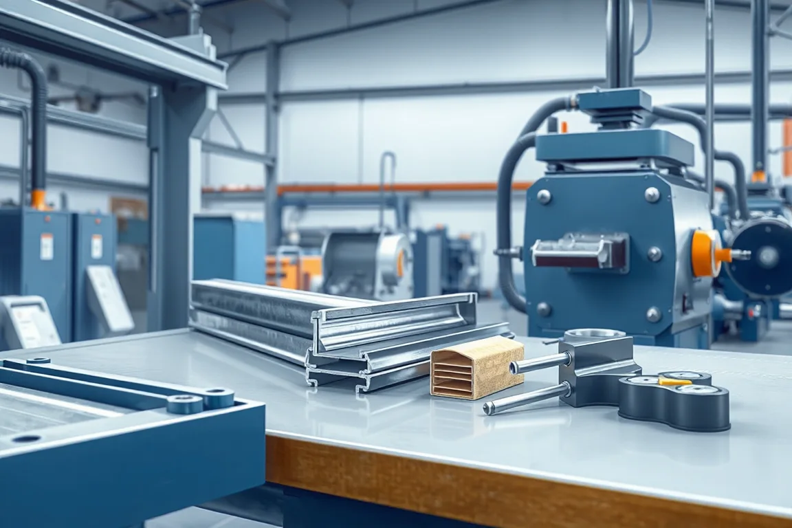
Choosing a solar roll forming machine starts with the part you must produce, not the machine listing. A solar mounting system may use roll-formed steel rails, struts, purlins or ground posts, but not every photovoltaic component is roll formed: a module frame is often an aluminum extrusion, while a steel rail or post is commonly cold formed from coated strip. Before machine selection, confirm the cross-section, material, joining method and load path. The machine must then be specified around that part and the mounting-system interfaces it must satisfy, including clamp fit, slot pattern and connection datums.
Start from the mounting design and finished part
A roll forming line produces a section from strip, but the mounting-system designer defines what the section must do. The drawing should show the base-metal thickness and grade, the coated condition, the slot and hole pattern, and the datums that locate clamps, bolts or other hardware. If the section drawing and the hardware drawings do not share the same datums, a machine can produce an apparently good profile that still fails at assembly. Treat the mounting design, the section and the tooling as one decision package.
Profile and interface requirements
The profile is more than an outline. Rail sections often include lips, stiffening returns and slots that engage mounting hardware. Ground posts may have different wall thickness, end conditions and hole patterns. A machine specified for one section family may not reproduce another without new rolls or additional stations. The practical question is which features must be formed, which must be punched, and which can be added as secondary operations. If the profile relies on clamp engagement, the tooling must hold the dimensions that control that engagement across the production run.
Material thickness and grade: define the envelope
Coated structural steel behaves differently from uncoated strip because the coating affects friction, marking and cut-edge appearance. Aluminum extrusion is a separate process and should not be forced into a roll-forming comparison. Buyers should specify base-metal thickness, grade and coating, then ask the supplier to confirm the operating range for that envelope. A machine that forms one thickness acceptably may not form a substantially thicker or higher-strength strip without changes to stations, drive capacity or cutoff. The material envelope is a selection input, not a marketing claim.
Process sequence and machine interfaces
A typical sequence for a solar rail or post line includes leveling, connection punching, channel forming, cutoff and mounting-interface inspection. Each step has interfaces that matter. Leveling affects strip flatness before forming. Punching must reference the same datums as the section drawing, so hole and slot position remain consistent after forming. Forming stations bend the strip progressively; the number and arrangement of stations affect the achievable section and the sensitivity to material variation. Cutoff must suit the profile and the required end quality. Inspection at the end confirms clamp fit, slot position, straightness and cut-edge condition.
Cutting, cutoff and secondary operations
Cutoff choice follows the profile. A profile-supported cutoff is intended to leave a defined end condition; a different method may require secondary operations such as deburring or end forming. The selection question is whether the line produces the finished part in one flow or relies on equipment outside the quote. If secondary operations are needed, they belong in the same comparison. The end quality of a cut can affect how the rail fits into a bracket or how coating at the cut edge is treated. Agree on cut-length tolerance and end appearance before tooling is committed.
Output: accepted parts, not a headline rate
No verified model rating is available here. Define accepted output per shift using the actual profile, material and finished-part scope. A meaningful output figure counts parts that pass the acceptance checks, not the speed of the line alone. Changeover time for the intended product mix also affects usable output. If the line must run several rail or post sections, the changeover sequence and the number of parts that require tooling changes belong in the comparison. Output should be expressed as accepted parts per shift under a stated material and section family.
Power, controls and site integration
The buyer should state voltage, frequency and phase. Installed power requires a confirmed equipment schedule, because the line may include drives, hydraulics, punching, cutoff and controls. Controls affect setup, recipe management and diagnostic visibility, but the selection should focus on what is confirmed for the specified equipment. Site integration includes foundation or floor condition, material handling before and after the line, and how finished parts are inspected or packed. These factors can limit real output even when the forming section performs as intended.
Acceptance criteria and demonstration
Acceptance should be measurable and agreed before tooling. Check clamp fit, slot position, section straightness and cut-edge condition against the section drawing and the hardware drawings. A meaningful demonstration uses the intended material and section family, not a substitute. If a demonstration is not possible, request a documented tooling and process proposal that separates confirmed capability from proposed future options. Wind, snow, corrosion and foundation requirements must be evaluated by the mounting-system designer; the machine supplier confirms the formed part, not the structural adequacy of the mounting system.
How to compare machine alternatives
A useful comparison uses the same drawing revision and material envelope for every supplier. Compare the forming stations, punching arrangement, cutoff method, controls, changeover scope, required secondary equipment and acceptance measurements. One alternative may offer more forming stations and a wider material envelope; another may focus on a narrower section family with simpler changeover. A third may rely on external punching or cutting, which shifts cost and risk outside the line. The right choice depends on the intended product mix and on which interfaces must be controlled in-house.
Cost: what a quote should cover
Cost comparisons are only meaningful when the scope matches. A quote may include leveling, punching, forming, cutoff, controls, tooling for one section and installation support, or it may exclude some of these. Ask whether the tooling is dedicated to one profile, how many section families are covered, and which secondary operations are outside the line. Also ask what happens when the material envelope changes. The accepted-output cost is the total installed and operating cost divided by accepted parts, not the purchase price alone. This is why a lower initial quote can be more expensive if it excludes tooling, changeover or inspection equipment.
Commissioning, handover and documentation
Commissioning should confirm the line produces accepted parts under the agreed material and section. Handover documentation should include the section drawing revision, tooling list, setup parameters, maintenance points and acceptance records. If the supplier proposes future options, separate them from the confirmed configuration. A clear handover reduces the risk that the line is adjusted later without a common reference. Documentation should also identify which measurements are checked at the machine and which are checked at assembly.
FAQ
Can one solar roll forming machine produce both rails and ground posts?
Only if the tooling and stations are designed for both section families and the material envelope covers the thickness and grade used. Rails and posts often differ in wall thickness, section depth, hole pattern and end condition, so changeover scope is part of the selection. Ask for the changeover steps and the parts that remain common.
Should I choose a machine based on line speed?
Line speed alone does not define output. Accepted output per shift depends on the profile, material, changeover and inspection. A line that runs quickly but produces parts outside the acceptance limits is not delivering usable output. Compare accepted parts under the intended section and material.
How do I confirm the punches will align with the mounting hardware?
Punching must reference the same datums as the section drawing, and the hardware drawings should be checked against those datums. A hardware fit trial or a documented inspection plan can confirm slot position and clamp engagement before full production. If the drawings use different references, resolve that before tooling.
What material information should I provide to a supplier?
Provide the base-metal thickness, grade and coating type, and state the intended range if more than one is expected. Aluminum extrusion is a separate process, so confirm that the intended part is roll formed from steel strip. The supplier should confirm the operating range for the stated envelope.
What should be included in an acceptance test?
Acceptance should cover clamp fit, slot position, section straightness and cut-edge condition, using the intended material and section. Measurements should be agreed in advance and recorded. Structural wind, snow, corrosion and foundation requirements remain the responsibility of the mounting-system designer.
When does a secondary operation belong in the quote?
If the line does not produce the finished part in one flow, any deburring, end forming, additional punching or separate cutting belongs in the same comparison. Otherwise the quote may appear complete while the real production path depends on equipment outside it.
Practical selection checklist
- Confirm the part is roll formed from steel strip, not an aluminum extrusion or another process.
- Collect the latest section drawing, hardware drawings and material specification.
- State base-metal thickness, grade and coating, and the intended range.
- Define the slot and hole pattern and the datums that control clamp engagement.
- Agree acceptance measurements for clamp fit, slot position, straightness and cut-edge condition.
- Compare the same material, section family and finished-part scope across suppliers.
- Clarify whether leveling, punching, forming, cutoff, controls and tooling are included.
- Identify any secondary operations and the equipment they require.
- Request a changeover demonstration or documented changeover scope for the product mix.
- Separate confirmed capability from proposed future options.
- State voltage, frequency and phase, and request a confirmed equipment schedule for installed power.
- Plan commissioning, handover documentation and the inspection points used at the machine and at assembly.
The selection decision is ultimately about matching a forming line to a defined section and a defined mounting interface. When the drawing, material envelope, tooling scope and acceptance criteria are aligned, the machine choice becomes a testable engineering decision rather than a comparison of unverified claims.
Continue your research
- Solar Mounting Roll Forming Machines
- Solar Strut Channel Roll Forming Machine
- Solar Mounting Rail Roll Forming Machine
- Solar C Channel Roll Forming Machine
- Solar U Channel Roll Forming Machine
- Solar Hat Channel Roll Forming Machine
- How Solar roll forming machine Works
- Solar roll forming machine Price: What Affects the Cost?
- Materials and Thickness for Solar roll forming machine