
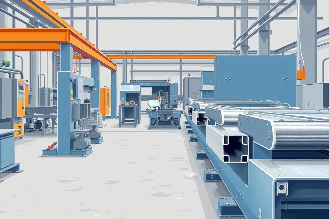
A solar roll forming machine converts flat or pre-slotted steel coil into a continuous mounting profile — typically a rail, strut, purlin or ground post — by pulling the strip through a series of powered roll stands that progressively bend the cross-section. In the sequence used for photovoltaic support profiles, the strip first passes a leveler, then a punching or notching station that creates connection holes and slots, then the forming stands that build the channel or rail shape, then a cutoff that severs finished lengths, and finally an inspection point where the mounting interface is checked. Each of those stages is a process boundary with its own tooling, its own accuracy contribution and its own interface to the next stage.
The important point for a buyer is that the machine is only one part of the manufacturing route. Some operations are integrated into the line, some are manual and some happen in a different cell entirely. Understanding how the machine works means understanding which operations are physically inside it and which have been left outside.
What the machine actually transforms
The input is coil, not a stack of cut blanks. Coil width, coil weight and the strip's flatness all affect how well the line can hold a section. The material is normally a coated structural steel strip; aluminum module frames, by contrast, are usually extrusions rather than roll-formed parts, so an aluminum frame is a different process route. Before selecting a line, confirm the cross-section, material and joining method, because those three facts determine whether roll forming is the appropriate process at all.
The output is a finished cut length of profile with holes and slots in defined positions. That part is a component. It is not yet a mounting system — wind, snow, corrosion and foundation performance belong to the mounting-system designer, not to the forming line. The line produces geometry; the system designer validates structural and durability behaviour.
Stage one: leveling and strip preparation
Coil often carries residual curvature, edge wave or coil-set. A leveler introduces controlled reverse bending so the strip enters the forming stands flat and with consistent width. If leveling is inadequate, the resulting section can twist or bow regardless of how well the rolls are set, because the error is already present before forming begins.
This stage also sets the datum for everything downstream. Where the strip edge is referenced determines whether punched holes and formed lips stay in the intended relationship. A common cause of field fit problems is a mismatch between the datum used in punching and the datum used in the section drawing.
Stage two: punching and notching connection features
Solar mounting profiles carry slots and holes that locate clamps, splice plates and base connections. In an integrated line, these are produced by punches or notches positioned before the forming stands, while the strip is still flat. Punching flat strip is usually easier to tool than punching a formed channel, but it means the hole position must account for how the material will flow and stretch through the subsequent bends.
The critical interface here is datum consistency. If the punch references one edge and the forming rolls reference another, slot positions will drift relative to the section. A practical acceptance check is a hardware fit trial: place the actual clamp, bolt or splice hardware on the finished profile and confirm engagement, slot alignment and edge distance. That trial tests the whole chain at once, not just the punch.
Stage three: progressive forming of the section
Forming happens in a sequence of stands, each making a small bend increment. The number of passes, the roll geometry and the bend sequence are chosen for the specific profile; a rail with return lips, stiffening ribs or a closed-ish channel needs a different pass schedule from a simple open strut. Each stand grips the strip and re-references it, so the strip must be supported and guided consistently or the section will twist, oil-can or develop edge ripple.
Tooling design decisions here have downstream consequences. Aggressive bend increments save stands but raise the risk of cracking in coated steel. Gentle increments control strain but require more stands and more floor space. Neither choice is universally correct; it depends on the grade, thickness and coating, and on the minimum bend radius the material tolerates.
Stage four: cutoff and end condition
The cutoff separates finished lengths from the running strip. Two questions matter. First, does the cut method suit the profile, or will it crush or distort the section at the cut plane? Second, what end quality does the next operation require — a square clean end, a deburred edge, an end notch or a swaged connection feature? Any secondary operation needs to be named in the layout and assigned to an owner, because a cutoff that produces a raw end does not deliver a finished connection.
Stage five: mounting-interface inspection
Inspection closes the loop. Meaningful checks include slot position relative to the section datums, section straightness, clamp fit and cut-edge condition. These are interface checks, not cosmetic ones: a rail that fits a clamp in the factory trial is more likely to assemble on site. The inspection station should reference the same datums used in the section drawing so that a deviation is traceable to a specific stage rather than being an unexplained dimensional result.
What the sequence diagram leaves out
A process diagram showing leveling, punching, forming, cutoff and inspection is a physical sequence, not the complete manufacturing route. It omits coil handling, scrap removal, coating touch-up, deburring, packaging, hardware supply and any post-cut machining or assembly. An operation omitted from a quotation still has to happen somewhere. Ask who owns each omitted step, who supplies its tooling and who is accountable for the interface between steps.
Comparing alternatives: integrated versus split operations
Integration and separate offline operations each have a place. Punching in line keeps hole position locked to the forming datum and reduces handling, but it ties the line to one hole pattern and makes changeover harder. Punching offline, on a separate press, allows more flexible patterns and lets the forming line run continuously, but it introduces a re-referencing step and additional handling between processes. Similarly, in-line cutoff supports continuous output, while sawing or secondary machining after the line can produce end features the cutoff cannot. The trade-off is between datum integrity and flexibility, and the right balance depends on how many different profiles and patterns are needed and how tightly the connection tolerances must hold.
A practical checklist for evaluating a proposed line
- Identify the input and output of each station, and mark where the strip is gripped, referenced, punched, bent, cut, joined or inspected.
- Distinguish the line's physical sequence from the complete manufacturing route, and list every operation that happens outside the line.
- Confirm how the part is referenced again after cutting or after any secondary operation.
- Check that punch positions and section dimensions reference the same datum.
- Ask for a hardware fit trial using the actual clamp, bolt and splice hardware.
- Define accepted output per shift using the actual profile and material, not a general figure.
- Confirm how cutoff-end condition meets the connection requirement, or name the secondary operation that finishes it.
- State the required voltage, frequency and phase, and obtain a confirmed equipment schedule for installed power.
- Have the mounting-system designer confirm wind, snow, corrosion and foundation requirements for the finished component.
Frequently asked questions
Is a roll-formed rail the same as an aluminum module frame?
No. A photovoltaic module's aluminum frame is usually produced by extrusion, which is a different process with different tooling and tolerances. A cold-formed steel section can be a suitable component for mounting rails or posts, but the cross-section, material and joining method should be confirmed before assuming roll forming applies.
Why does the leveler matter if the forming rolls set the final shape?
Because forming rolls cannot remove curvature that is already in the strip. Residual coil-set or edge wave propagates through every stand and shows up as twist or bow in the finished section. Leveling establishes a flat, consistent starting condition so the forming stages work from a stable input.
Why is punch position tied to the section drawing rather than to the strip?
Because the finished part must fit the connection hardware. If punches reference the strip edge while the section references a formed feature, the two datums can diverge during forming, shifting slots relative to the profile. Using one shared datum makes hole position traceable and repeatable.
What does accepted output per shift actually depend on?
It depends on the specific profile, the material and thickness, how many punching and cutoff operations are included, and how much changeover and inspection time is built in. A meaningful figure is defined against one actual profile and material combination, then verified on that basis.
Can one line produce rails, struts, purlins and ground posts?
Often the architecture can be configured for more than one section, but each family has its own interfaces and loads, and each needs its own roll tooling and potentially different punching and cutoff arrangements. Whether a single line is practical depends on section similarity, changeover frequency and the tooling budget.
What should be confirmed before accepting a finished component?
Clamp fit, slot position, section straightness and cut-edge condition are the practical interface checks. Structural, corrosion and foundation performance are separate: those must be evaluated by the mounting-system designer, not inferred from how well the profile formed.
Continue your research
- Solar Mounting Roll Forming Machines
- Solar Strut Channel Roll Forming Machine
- Solar Mounting Rail Roll Forming Machine
- Solar C Channel Roll Forming Machine
- Solar U Channel Roll Forming Machine
- Solar Hat Channel Roll Forming Machine
- How To Choose a Solar roll forming machine
- Solar roll forming machine Price: What Affects the Cost?
- Materials and Thickness for Solar roll forming machine