
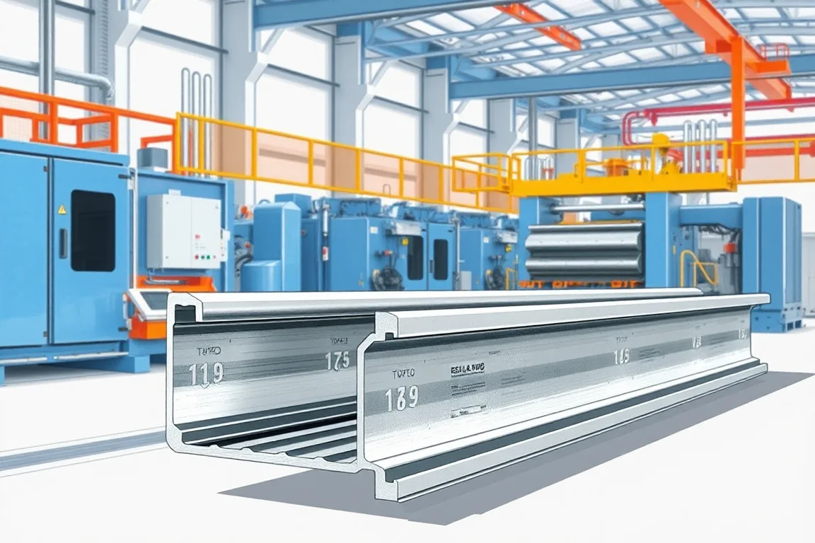
A solar mounting rail roll forming machine produces the long metal profiles used to connect photovoltaic modules with a specified support arrangement. The rail may contain clamp interfaces, mounting slots, splices or other functional features. Its geometry should follow the mounting-system design rather than a generic rail shape.
Before choosing roll forming, confirm that the proposed rail is a sheet-derived profile suited to progressive bending. Some familiar solar rails are made by extrusion and contain geometry that cannot be copied directly with ordinary roll tools. Process selection and profile design need to be considered together.
Which mounting rail is being manufactured?
Identify the rail's role in the complete system: how it supports module clamps, how it connects to the underlying brackets and how adjacent lengths join. A roof-mounted rail and a ground-structure member may share a broad application while using different interfaces and material requirements.
Do not confuse the mounting rail with the perimeter frame around the module. The frame belongs to the module assembly, while the rail is part of the support system. Their machinery and acceptance requirements should be scoped separately.
When is roll forming an appropriate process?
Roll forming is worth reviewing for a repeated longitudinal sheet profile with suitable bend development and production volume. The design must allow the tools to create the required returns and contact surfaces progressively. Enclosed or intricate features may need another process or a redesigned construction.
Compare roll forming with extrusion or fabricated alternatives using the actual rail drawing, material and order mix. A process comparison should include secondary holes, cutting, joining and finish, not only the cost of creating the main cross-section.
A process change also needs an engineering review of the product. Replacing an extruded rail with a superficially similar formed section is not a manufacturing substitution that can be made solely by matching outside dimensions.
What should the functional drawing show?
- Complete section, bends and any seams or joined elements.
- Module-clamp seating and retention interfaces.
- Bracket and roof or ground-support connection features.
- Splice geometry and required end relationships.
- Material, thickness and corrosion-protection route.
- Lengths, identification and final inspection requirements.
Supply the intended clamps, brackets and splice samples. Their actual contact surfaces should be visible in the drawing package. A rail dimensioned only by overall height and width leaves the most important tooling targets undefined.
How does the manufacturing route work?
The line prepares and guides the strip, creates required features, progressively forms the rail and cuts it into ordered lengths. Additional seam joining or fabrication belongs in the route only where the product design requires it. The proposal should identify every included operation.
- Verify material and the released rail configuration.
- Present the strip with controlled orientation and guidance.
- Produce required mounting and splice features.
- Develop the rail's bends and functional interfaces.
- Complete any specified joining or secondary operation.
- Cut, inspect and identify accepted rail lengths.
Ask how the process maintains the relationship between the upper clamp interface and lower mounting references. Inspecting them independently can miss a positional mismatch within the complete section.
How should material and finish be defined?
Specify grade or alloy, base-metal thickness, strip width and finish for each rail family. Material response affects the formed section and its springback, while the finish affects handling and the final interfaces. Equal thickness does not make different metals interchangeable.
Identify whether corrosion protection is applied before or after fabrication. Coordinate that route with holes, cut edges, joints and final fit. The equipment enquiry should not invent a durability claim from a coating name alone; it should follow the specified component requirements.
Keep coil and finishing records connected to the rail order. This makes later dimensional or surface investigations more practical and helps prevent similar-looking materials from being mixed in dispatch.
What matters about clamp and bracket interfaces?
Use production-intent mounting hardware in the trial. Check that it seats, locates and engages according to the selected system's assembly method. Inspect contact surfaces and local clearances, not only whether a bolt can be inserted.
Where the rail has different upper and lower connections, test both. A correct module-clamp interface does not prove the bracket connection is correct. Record any unplanned forcing, reshaping or hole modification as a deviation.
The fit trial establishes manufacturing compatibility. Connection strength, electrical bonding and complete mounting-system performance require the relevant design and verification. Those should be assigned explicitly rather than inferred from a visually successful assembly.
How should mounting slots be controlled?
Provide the actual feature schedule with dimensions and references to the finished rail. Repeated slots, project-specific holes and splice features may need different control logic. Identify clear zones near ends and bends where the drawing requires them.
Inspect the completed profile for feature position, burrs and distortion. If punching precedes forming, confirm that the final spatial relationship remains correct. A flat-strip pattern check is useful but does not replace final component inspection.
For several rail lengths, demonstrate the corresponding pattern changes. A controller capable of changing cut length does not automatically establish that all end-related features move correctly.
What should a splice trial include?
Join normal production rail lengths with the specified splice and fasteners. Check alignment of the rail section and the continuity of relevant mounting surfaces. Inspect both the fit before fastening and the condition after the intended assembly procedure.
End flare, burrs or local distortion can affect splice insertion even when the main section is correct. Compare end measurements with the middle of the rail. Do not compensate for a faulty end by modifying the splice during acceptance.
Keep any movement allowance or structural behavior tied to the system design. A loose or sliding-looking fit should not be interpreted as an approved thermal-movement feature without the relevant product definition.
How much product flexibility is practical?
Separate changes in length and hole pattern from changes in the main section. The former may handle some variations through controls or adjustments, while a new clamp interface or bend arrangement requires tools. Request a clear configuration matrix.
Demonstrate the changes most representative of real orders and a return to the original accepted setup. Include hardware fit and inspection in first-good-product time. A quick mechanical adjustment that needs prolonged correction afterward is not a complete changeover result.
What should long-rail handling prevent?
Provide support through cutoff, inspection and bundle removal. Long rails can be damaged or appear distorted under inconsistent support, so establish measurement and handling conditions. Protect functional edges and finished surfaces during nesting.
Labels should distinguish section, pattern, material, finish and length. Similar rails for different clamp or bracket systems should not be mixed. Keep rejected and setup pieces outside the accepted bundle flow.
Where kits are supplied to projects, define the bundle sequence and identification needed by the installer. A technically correct rail can still create avoidable work if its order reference is lost.
How should output and acceptance be compared?
Use accepted rail lengths for a representative order with required features and normal inspection active. Coil changes, pattern changes, cutoff and collection all affect the practical rate. Do not compare a plain-profile speed with a feature-intensive rail order.
- Measure the complete section and functional hardware interfaces.
- Verify features from the finished datums.
- Check length, straightness and end condition.
- Assemble specified clamps, brackets and splices.
- Demonstrate required configuration changes.
- Inspect final finish and packed rails.
- Record accepted quantities and unresolved deviations.
In quotations, separate profile tools, feature equipment, joining where required, handling and commissioning. Identify product qualification responsibilities and any purchased hardware outside the line supply.
Frequently asked questions
Can any aluminum solar rail be roll formed?
No. Some rail geometries are designed for extrusion. Review the section, material and tool access before selecting a process. A change to a formed construction needs its own product engineering review.
Is the mounting rail the module frame?
No. The rail belongs to the support arrangement, while the perimeter frame belongs to the module assembly. They have different interfaces and manufacturing requirements and should not be combined under one vague frame-machine scope.
Can one rail accept every solar clamp?
Not automatically. Clamp contact and retention geometry vary. Use the specified hardware during tooling review and acceptance, and verify both module-side and support-side interfaces where applicable.
Does a splice fit establish connection capacity?
No. Fit is a manufacturing check. Structural performance and any movement behavior follow the selected system design and verification. Do not infer them from the ability to assemble two lengths.
Can hole patterns change without new tooling?
Only within the installed tools and control arrangement. New shapes or positions may require additional equipment or setup. Provide the full pattern family and demonstrate the required transitions.
What should an enquiry include?
Send the complete rail and hardware drawings, materials, finish, feature schedules, lengths and order mix. Add splice and packing requirements. This allows a useful comparison of the entire mounting-rail production route.

Continue your research
- Solar Mounting Roll Forming Machines
- Solar Strut Channel Roll Forming Machine
- Solar Panel Frame Roll Forming Machine
- Solar C Channel Roll Forming Machine
- Solar U Channel Roll Forming Machine
- Solar Hat Channel Roll Forming Machine
- How Solar roll forming machine Works
- How To Choose a Solar roll forming machine
- Solar roll forming machine Price: What Affects the Cost?
Configuration & specification inputs
Match the configuration to your section drawing, material and production requirements.
| Parameter | Requirement / confirmation needed |
|---|---|
| Profile geometry | Mounting rail section with module-clamp, support-bracket and splice interfaces |
| Material | Design-specified grade or alloy, thickness and final protection route |
| Thickness & grade | Review the complete material/profile combination for roll-forming feasibility |
| Process route | Feature-making, progressive rail forming, required joining, cutoff and component inspection |
| Cutting | Control end geometry for splice insertion and finished feature references |
| Output | Accepted hardware-compatible rails for the real pattern and length mix |
| Electrical supply | Confirm utilities for forming, features, joining where required and long-rail handling |
| Acceptance | Measure all interfaces, assemble intended clamps/brackets/splices and verify profile recovery |