
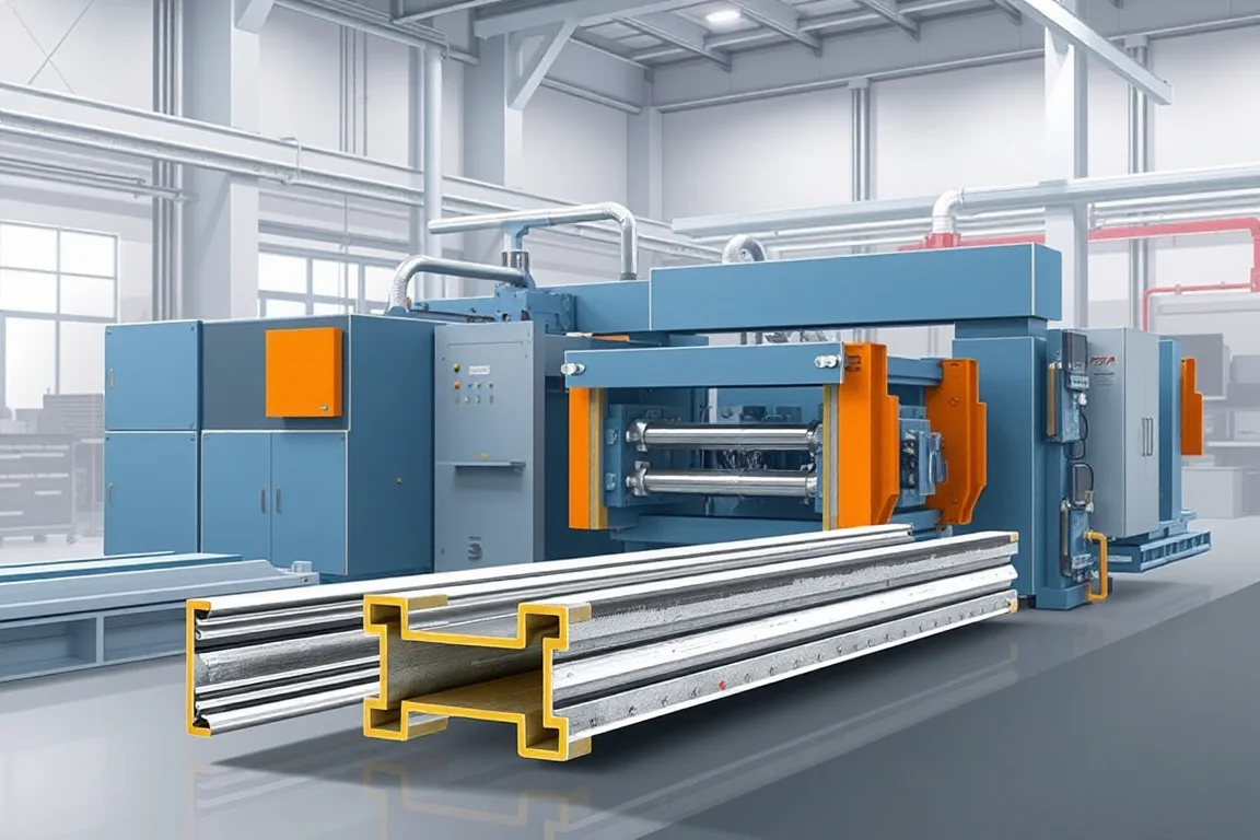
A PV bracket roll forming machine is selected to produce the defined longitudinal profiles used within a photovoltaic support structure. The term bracket can also refer to short stamped or fabricated connectors, so the first task is to separate the long roll-formed members from parts that need another manufacturing route.
A useful project brief maps each support component to its drawing, material, features and assembly role. This prevents a single channel former from being mistaken for equipment that manufactures an entire mounting system, including clamps, fasteners, posts and specialized connections.
Which PV support components suit the proposed line?
Repeated C, U, hat, strut or other sheet-derived profiles can be reviewed for roll forming when their geometry and production volume suit progressive bending. Each profile still needs its own feasibility and tooling assessment. Sharing a solar application does not make the sections interchangeable.
Short angle brackets, complex stamped connectors, cast parts or extruded components may use different processes. Identify them separately and decide whether they are made in-house or purchased. The equipment selection should follow the actual component catalogue rather than an overly broad bracket-machine label.
How should the support-system interfaces be described?
Show where each member connects to modules, rails, posts, foundations or roof attachments, as applicable to the selected design. The connection surfaces and feature locations are the functional targets for manufacturing. A general arrangement drawing is useful but should be supported by controlled component drawings.
- Complete section and bend geometry.
- Mounting faces, slots and holes.
- Splice and bracket interfaces.
- Material grade, thickness and finish.
- Lengths, end details and handed variants.
- Component identification within the assembly.
Provide representative mating components for trial assembly. This helps expose hidden clearances or access requirements that an isolated section sketch may not communicate.
What should the product matrix contain?
List each profile with its actual material, width, thickness, length and feature combinations. Separate programmable variations from changes requiring mechanical adjustment or tools. A machine's individual maximum values should not be combined into an assumed universal production envelope.
Include the expected order mix and frequency of changes. A dedicated route can suit sustained demand for one support member, while changeable tooling may serve a broader but lower-volume catalogue. The decision depends on real schedules and component balance.
Identify future products as development items rather than treating them as already supported. Their geometry and material may require another pass design, feature tool or production process.
How does the roll-formed member route work?
- Release the correct component drawing, material and feature program.
- Identify and present the coil to the line.
- Produce the required mounting features in the agreed sequence.
- Develop the section progressively through its bends and returns.
- Cut and complete the specified end operations.
- Inspect, identify and group accepted members for assembly or finishing.
The detailed placement of punching, forming and cutting depends on the equipment. Ask how the final feature datums are maintained and which operations remain outside the line. The finished component, not a partly formed sample, should define acceptance.
How should mounting holes and slots be controlled?
Features establish the connection between members and hardware. Specify their shape, orientation, spacing and relationship to the ends and bends. Repeated slots and project-specific attachment holes may need different control functions.
Inspect the completed profile for position, burrs and local distortion. If features are produced before forming, confirm their final spatial relationship. A correct flat pattern can still become an incorrect component if its forming references are wrong.
For mirrored or handed members, include clear identification and an orientation check. Two parts may share a section and length while having incompatible feature directions. Visual similarity should not be used as the main sorting method.
What material and corrosion-protection inputs are needed?
Specify grade or alloy, base-metal thickness, input width and finish for each support component. Material selection belongs to the approved structure and environment requirements. The machine review should use those specifications rather than inventing a generic outdoor durability claim.
Define the finishing route before trial planning. Prefinished strip and post-fabrication coating involve different inspection and handling questions. Coordinate holes, cut edges, joints and hardware fit with the product's intended final condition.
Retain coil and finishing identity through component storage. This makes it possible to distinguish similar sections made for different material specifications or project requirements.
What configuration flexibility should be demonstrated?
Separate length changes, pattern changes, width adjustments and new profile geometry. The controller may manage some variations, while other changes require rolls, guides, punches or cutting tools. Request a clear configuration matrix with the work involved in each transition.
Demonstrate a representative change and return to the original product. Include the first accepted component and its mating-hardware check. Timing only a powered adjustment can omit the practical work needed to restore dimensional and feature accuracy.
For a shared line, account for tool storage and safe handling. Flexibility is useful only when the production team can repeat each configuration without undocumented correction.
How should a representative support assembly be checked?
Assemble the selected members with their intended brackets, splices and hardware under the defined procedure. Check seating surfaces, hole alignment and component orientation. Record unplanned force or local modification rather than hiding it in a completed assembly photograph.
Measure the individual components as well as the assembly. If the frame does not align, separate profile geometry, feature location and fixture or assembly errors. Adjusting one member to compensate for an incorrect mating part can spread the problem across the catalogue.
The trial verifies manufacturing compatibility. Structural capacity, wind or snow requirements, foundation behavior and electrical bonding remain responsibilities of the complete mounting-system design and its relevant verification.
What secondary operations need explicit scope?
Some members require local bending, welding, end notching or another operation after the longitudinal profile is made. Short connectors may be produced on separate punching or bending equipment. Identify each operation and its inspection stage.
If the project supplies complete mounting kits, define the purchased fasteners, clamps and other hardware as part of the bill of materials. A factory capable of forming every long section can still fail to deliver a usable kit when the connection parts are missing or incompatible.
Keep intermediate and finished components distinguishable. A formed blank awaiting drilling or coating should not be counted as a completed order item.
How should storage and packing support project supply?
Group components by section, length, pattern and material, then by project where required. Protect functional edges and finishes during nesting and movement. Similar-looking members should carry clear references that survive the finishing and dispatch route.
For kits, agree whether packing follows installation zones, assembly groups or another practical sequence. The best production count is not always the best delivery order. Coordinating the two reduces sorting work and the risk of missing components at the receiving end.
What is a meaningful capacity comparison?
Use accepted components or complete kits for a stated bill of materials and order mix. Punching, forming, secondary work, finishing and packing can each constrain the result. An isolated channel-forming speed does not describe the output of a complete PV bracket project.
For planning only, a kit requiring four rails, six supports and specified connectors is incomplete if one support is missing, even if extra rails are available. The actual ratios come from the approved design. Use that component balance when comparing shared and dedicated equipment.
Separate common line equipment, product-specific tools, secondary machines and purchased components in quotations. Identify commissioning, inspection aids and future-product development so the total project scope is visible.
What should acceptance include?
- Representative products from every included profile family.
- Material identification and final finish condition.
- Section, feature, length and end measurements.
- Correct orientation of handed components.
- Assembly with the intended hardware and mating members.
- Required production changes and repeatable recovery.
- Identified accepted components or complete kits after normal handling.
Retain drawings, settings and reference assemblies together. They establish the baseline for repeat orders without implying that a machine trial replaces the engineering of the solar support structure.
Frequently asked questions
Does PV bracket mean one standard profile?
No. The term can cover long support members and short connectors made by different processes. Start with the component drawings and assembly role so the equipment proposal addresses the correct products.
Can one roll former make a complete mounting system?
Not automatically. Clamps, fasteners, posts and specialized connectors may require separate equipment or suppliers. Map every component to a production or purchasing route before calling the package complete.
Can every dimension be changed automatically?
Only those supported by the installed tooling and controls. New bends, returns or connection faces may require different tools. Ask for a configuration matrix and demonstrate the changes relevant to actual orders.
Does a trial assembly establish wind capacity?
No. It checks manufacturing fit and alignment. Structural performance and project suitability require the applicable complete-system engineering and evidence beyond the roll-forming acceptance run.
Why separate intermediate blanks from finished parts?
Some components still need holes, joining, finishing or inspection after forming. Counting them as complete can conceal missing work and create incomplete kits. Clear identification keeps the production status practical and visible.
What is the best starting document?
Create a component matrix with drawings, materials, features, lengths, quantities and finishing requirements. Add the assembly bill of materials and packing plan. This provides a clear basis for selecting and balancing the manufacturing routes.

Continue your research
- Solar Mounting Roll Forming Machines
- Solar Strut Channel Roll Forming Machine
- Solar Mounting Rail Roll Forming Machine
- Solar C Channel Roll Forming Machine
- Solar U Channel Roll Forming Machine
- Solar Hat Channel Roll Forming Machine
- How Solar roll forming machine Works
- How To Choose a Solar roll forming machine
- Solar roll forming machine Price: What Affects the Cost?
Configuration & specification inputs
Match the configuration to your section drawing, material and production requirements.
| Parameter | Requirement / confirmation needed |
|---|---|
| Profile geometry | Controlled catalogue of roll-formed PV members and separately scoped connectors |
| Material | Component-specific material and protection requirements linked through finishing |
| Thickness & grade | Approved grade, thickness and width combinations by support profile |
| Process route | Component-specific feature/forming routes, secondary work, final inspection and kit grouping |
| Cutting | Coordinate lengths, handed patterns and end operations with assembly drawings |
| Output | Accepted components or complete kits for the stated bill of materials |
| Electrical supply | Develop utilities from included forming, feature, secondary and handling equipment |
| Acceptance | Measure profile and feature datums, check handed orientation and assemble intended support hardware |