
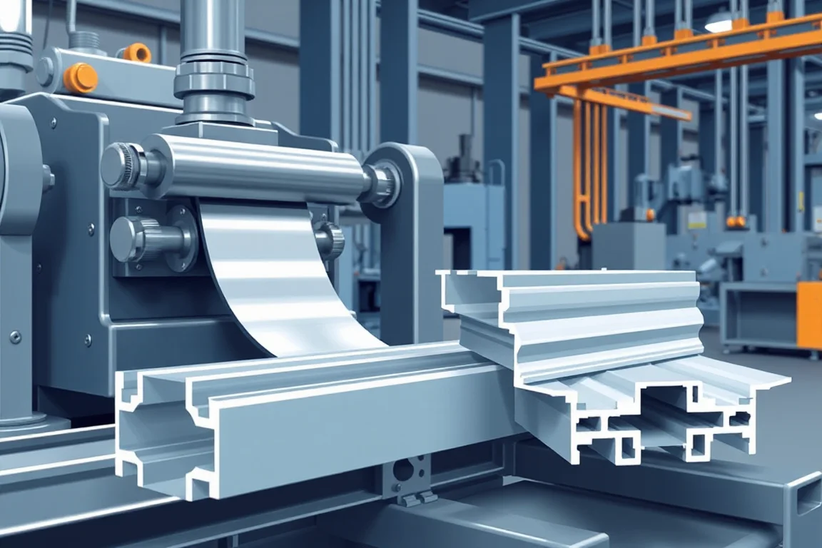
What roller and tooling design actually controls
On a solar roll forming machine, the roller tooling is the part of the equipment that turns flat strip into the rail or post section the mounting system needs. It does not decide whether a photovoltaic module frame is roll formed; that frame is typically an aluminium extrusion from a separate process. The roller and tooling design for this machine therefore controls the functional geometry of the cold formed support member: bend radii, web and flange orientation, lip form, slot location and the final cut edge.
Design begins with the section drawing, not with a roll count. The drawing defines connection datums, clamp engagement surfaces, slot pattern and mating hardware. Tooling design then maps those features onto a forming sequence and onto punch, cutoff and inspection stations. If the roll tools and the punching tools reference different datums, the finished rail can meet a nominal section while failing a hardware fit trial.
How the forming sequence develops the section
A typical process for a solar rail or post begins with strip leveling, proceeds through connection punching and channel forming, ends with cutoff, and then moves to mounting interface inspection. Each step has an interface with the next.
Leveling establishes a stable strip condition before the first bend. If the strip enters the first forming pass with a coil set or cross bow, later passes may compensate by distorting a different feature. The forming passes then develop the bends in a planned order. A common approach forms a shallow channel first, then brings flanges and lips into position, so that the strip is always located by surfaces that remain stable through the sequence. Springback is addressed by tool geometry and by the order of bends, not by a single adjustment. Material variation, including yield strength and coating condition, changes how much the strip returns after each pass; the design should account for that variation across the range the buyer and supplier agree to verify.
Punching and cutoff are not separate from forming design. Connection holes and slots should be produced while the strip is positively located, using the same datum scheme as the section drawing. Cutoff must suit the profile so that the cut end is square enough for the intended connection and does not crush the section. The cut length and end quality are part of the accepted output definition, together with any secondary operations.
Why functional geometry comes before roll count
A roll count without a forming design does not demonstrate quality. The useful questions are how each bend develops, which surfaces locate the strip, how springback is addressed, and how tooling is changed when the profile changes. Two machines with the same number of forming stations can produce very different sections because the pass sequence, roll diameters, shaft stiffness and locating strategy differ.
Start from the functional geometry: rail or post section, slot pattern, clamp engagement and connection datums. The roller tooling should be designed so that the surfaces that locate mounting hardware are formed and held consistently. Slots and lips often locate mounting hardware, so their position relative to the connection datum matters as much as the overall section shape. A hardware fit trial, using the intended clamp or bracket, is a practical check that the tooling produces the interface the mounting designer assumed.
Punch and cutoff tooling must share datums
Punch and cutoff tooling are often treated as accessories, but they belong in the same design review as the roll tools. If punches reference the section web while the roll tools locate the strip by a flange lip, the slot position can drift when material varies. The design should define a single datum scheme from the section drawing through forming, punching and cutoff.
Cutoff tooling should be selected for the profile, not only for the strip thickness. A cutoff that supports the section during the cut helps maintain end quality; a cutoff that relies on the section to resist deformation may produce a crushed or torn end. Cut lengths and end condition are acceptance items, and secondary operations such as deburring or additional punching should be identified in the process description rather than assumed.
Tool change and setup as part of the design
Tooling design includes how tools are changed and how the accepted setup is recorded. Roll forming machines that run more than one solar profile need a repeatable change method: identifiable tool sets, documented shim or spacer arrangements, and a setup record that ties the tool identification to the accepted output. Production should not depend on an undocumented adjustment made by one operator.
Material variation and access to the final section also belong in the design. If the final forming passes are difficult to reach, setup and inspection become unreliable. The design should allow the strip to be threaded, the section to be observed, and the tooling to be maintained without disturbing unrelated adjustments.
Alternatives and tradeoffs in roller tooling design
There are broadly different approaches to tooling a solar rail or post, and each carries tradeoffs.
- Fixed dedicated tooling: designed for one section and one material range. It can provide stable location and fewer setup decisions, but changing to a different rail or post may require a new tool set.
- Segmented or adjustable tooling: intended to cover a family of related sections. It can reduce tooling inventory, but the added adjustment points create more opportunities for setup drift and usually demand a stronger setup record.
- Progressive forming with in-line punching: locates holes and slots while the strip is in the forming line. It can reduce handling, but it ties punch maintenance and forming setup together.
- Forming followed by separate punching or secondary operations: separates the two processes. It can simplify each station, but it introduces a second locating step and increases the risk that hole position and section datum diverge.
The right choice depends on how many sections the operation expects to run, how tightly the clamp and slot interfaces must be held, and how much setup discipline exists in production. A roll count alone does not distinguish between these approaches.
Acceptance checks for the formed solar rail or post
Acceptance should be defined against the actual profile and material, not against a generic machine rating. A practical acceptance plan includes:
- Clamp fit, using the intended mounting hardware or a representative gauge.
- Slot position relative to the connection datum in the section drawing.
- Section straightness along the rail or post.
- Cut-edge condition, including squareness and freedom from crushing or tearing.
- Repeatability across the agreed material range and profile extremes.
These checks address the component as produced. They do not evaluate wind, snow, corrosion or foundation requirements; those must be evaluated by the mounting-system designer. A cold formed steel section can be a suitable component, but its suitability depends on the mounting design and the loads it receives.
Practical checklist before committing to a tooling design
- Identify the functional dimensions and every mating part.
- Confirm the cross-section drawing, material and joining method, and distinguish roll formed parts from extrusions.
- Review punch and cutoff tooling together with the roll tools, using one datum scheme.
- Ask how each bend develops and how springback is addressed.
- Ask which surfaces locate the strip in each forming pass.
- Verify tool changes using the agreed material and profile extremes.
- Plan a hardware fit trial with the intended clamp or bracket.
- Record the accepted setup and tool identification together.
- Define accepted output per shift with the actual profile and material, without relying on an unverified model rating.
- Confirm the electrical supply requirements and installed power with a confirmed equipment schedule.
- State the base-metal thickness and grade; operating range requires supplier verification.
FAQ: roller and tooling design questions
Does more forming stations mean better tooling?
No. The number of stations is only a count. What matters is the pass sequence, the locating strategy, how springback is managed and how punch and cutoff tooling share datums. A design with fewer stations can produce a more consistent section if the bends are developed correctly.
Why does slot position drift even when the section looks correct?
Slot position usually drifts when the punch station references a different surface than the forming stations locate. Material variation can then shift the strip relative to the punch. The diagnostic evidence is the relationship between slot location and the connection datum across multiple pieces, not just the overall section shape.
Can the same roller tooling run a rail and a post?
Only if the tooling was designed for that family of sections and the forming sequence supports both. Segmented or adjustable tooling may cover related profiles, but it adds setup points that need documented control. A dedicated tool set is often more stable for one section but less flexible for changeovers.
How is springback addressed in solar roll forming tooling?
Springback is addressed through the bend sequence, roll geometry, and the way the strip is overformed or supported at each pass. Material yield strength and coating condition affect how much the strip returns, so the design should account for the agreed material range rather than a single sample.
Should punching be in-line or separate?
In-line punching can keep hole and slot location tied to the forming datums and reduce handling. Separate punching may simplify the forming line but introduces a second locating step and a risk that hole position and section datum diverge. The tradeoff is between process integration and setup simplicity.
What evidence shows that tooling design is acceptable?
Acceptance evidence includes clamp fit with the intended hardware, slot position relative to the connection datum, section straightness, cut-edge condition, and repeatability across the agreed material and profile extremes. The accepted setup and tool identification should be recorded together so production does not depend on an undocumented adjustment.
Continue your research
- Solar Mounting Roll Forming Machines
- Solar Strut Channel Roll Forming Machine
- Solar Mounting Rail Roll Forming Machine
- Solar C Channel Roll Forming Machine
- Solar U Channel Roll Forming Machine
- Solar Hat Channel Roll Forming Machine
- How Solar roll forming machine Works
- How To Choose a Solar roll forming machine
- Solar roll forming machine Price: What Affects the Cost?