
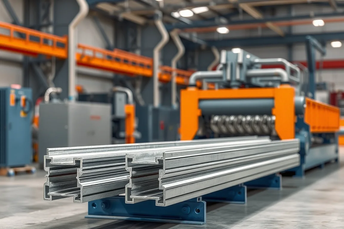
A solar strut channel roll forming machine produces the open channels used within a specified photovoltaic mounting arrangement. The important manufacturing features are the channel opening, inward returns, mounting slots and interfaces with nuts, clamps, brackets or splices. Their combined geometry determines whether the intended hardware can be assembled reliably.
The equipment should be selected around the actual mounting-system components. A common strut name or nominal size does not establish compatibility with every channel nut or clamp, and producing a channel does not by itself define the loading or durability of a solar installation.
What makes strut different from a plain C channel?
A strut channel typically includes functional inward edges that work with its fastening arrangement. Those returns and the opening between them are central production targets. A plain C-shaped section with similar outside dimensions may not provide the same seating or retention surfaces.
Specify the intended nut, clamp or other fastening component alongside the section drawing. Where serrations or another edge treatment are part of the design, include their geometry and inspection criteria. They should not be added simply because another strut product uses them.
Which drawings should define the machine?
- Web, sides, inward returns and channel opening.
- Functional contact surfaces for the specified hardware.
- Slot or hole patterns and their relationship to the ends.
- Material grade, thickness and coating route.
- Lengths, splice details and required end condition.
- Assembly references for the selected solar mounting arrangement.
Use clear internal and external dimensions. The opening and contact surfaces can matter more than a nominal overall width. Provide production-intent hardware samples so the tool review is based on the intended interface rather than a convenient substitute.
How is the channel formed?
The line guides the strip from the coil, creates required mounting features, progressively develops the sides and returns, cuts the ordered length and supports the finished channel. The actual sequence of punching and forming depends on the proposed equipment.
- Identify and present the specified coil.
- Guide the strip and produce the released feature pattern.
- Develop the web and side walls through the forming passes.
- Complete the inward returns and any included edge treatment.
- Cut the channel with appropriate support for its opening and lips.
- Inspect the profile and hardware fit before bundling.
Ask how the forming sequence controls the final return geometry. A useful explanation connects tool contact and material response to the surfaces that retain the hardware, rather than relying on roller count alone.
How should slots and holes be coordinated?
Provide the actual shapes, spacing and end references. A repeated slot pattern and a project-specific connection pattern create different control requirements. Specify whether the pattern continues through every length or includes clear zones and special end features.
Inspect the completed channel for feature position, burrs and local distortion. Slots produced before forming must remain correctly related to the final web and sides. A flat-strip check alone does not establish the delivered product.
Where different mounting projects use the same section with different patterns, keep the programs and product identification distinct. A correctly formed channel with the wrong slots is still the wrong component for the order.
What material combinations need review?
Specify grade or alloy, base-metal thickness, width and coating together. Forming tight functional returns in one material does not establish the same result in another. The trial plan should include the actual combinations required by the mounting-system catalogue.
Define the finishing route and final condition of the hardware-contact surfaces. A coating applied after fabrication can be relevant to fit, while prefinished material needs attention at bends and cut edges. Follow the component specification rather than assuming the routes are interchangeable.
Retain material identity through forming and finishing. If a later batch has a changed channel opening or hardware fit, compare stock, setup and finish with the accepted reference before altering the tools.
How should nut and clamp fit be tested?
Use the exact hardware specified for the mounting system. Check insertion, positioning and seating according to its intended assembly method. Inspect the channel at normal production lengths and near the ends, where cutting can affect the opening.
Record tightness, looseness, uneven seating and any need for local reshaping. A fitting forced into one selected short sample is not evidence of repeatable compatibility. Measurements of the returns and opening should accompany the assembly observations.
This trial addresses manufacturing fit. It does not replace the required verification of connection strength, grounding arrangements or the complete solar structure. Those responsibilities remain tied to the selected system design.
Can one line make several strut sizes?
A configured line may cover a size family through adjustment, changeable tools or multiple tool arrangements. Identify which web and side dimensions vary and whether the inward returns remain the same. Different opening or lip designs can require more than a width adjustment.
Request a matrix of guides, rolls, punches, cutoff parts and settings for each size. Demonstrate the transitions that reflect regular orders, including hardware fit after the change. Return to the original setup to verify recovery.
If back-to-back or other assembled channels are part of the catalogue, include their joining route separately. Producing an individual strut does not automatically provide a completed multi-piece member.
What should be checked at cutoff?
The cutting arrangement must preserve the inward returns and channel opening. Inspect local flare, crushing and burr condition after ordinary takeoff. Compare the end with a measurement farther along the same piece to distinguish cutting effects from a persistent profile error.
Test short and long products. Short lengths increase cutting and collection frequency, while long channels need adequate support and removal space. Both can affect the practical line configuration.
Where mounting hardware slides or enters from an end, the specified end condition is especially important. It should be demonstrated with the actual assembly method rather than assumed from a clean-looking cut surface.
How should packing preserve functional edges?
Define nesting orientation, bundle quantity and protection for the channel lips and finish. Tight packing should not change the opening or make sections difficult to separate. Check representative channels after normal bundle movement.
Labels should identify section, material, finish, pattern and length. Solar projects can use similar channels with different feature schedules, so a generic strut label is insufficient. Separate setup pieces and rejected parts from accepted stock.
What is a useful output and cost comparison?
Compare accepted channels for a representative order with the required slot pattern active. Punching, cutoff, coil changes, inspection and bundling can govern the result. A speed shown on plain unpunched material does not establish the output of the intended solar component.
Include the complete tooling family, feature equipment, coil handling, cutting and takeoff in quotations. Identify edge treatment, marking, joined-channel production and finishing as separate scope where required. This makes different levels of integration easier to compare.
For planning arithmetic only, 500 channels at 2.4 metres each contain 1,200 metres of finished section. That quantity does not determine the number of solar modules supported, because the mounting layout and component use are system-specific.
What should acceptance demonstrate?
- Controlled channel opening, returns and main section dimensions.
- Slot or hole position and edge condition.
- Hardware fit using the intended components.
- Length, end condition and straightness.
- Required size-pattern changes and recovered production.
- Final finish and bundle identification.
- Accepted output with normal inspection and handling.
Retain the hardware, channel samples and setup record together. A matched reference set is more useful for later troubleshooting than a loose channel without its intended nut or clamp.
Frequently asked questions
Can any channel nut fit a nominally matching strut?
Not necessarily. Opening, return and contact geometry can differ. Use the specified hardware during tooling and acceptance, and confirm the complete interface rather than relying on a nominal size label.
Are serrated edges always needed?
Only where they belong to the selected product design. Their geometry and production method should be specified. Adding serrations is not a universal improvement and may change the hardware interface.
Can the line make unpunched and slotted channels?
A configured route may cover both, but the control and tooling arrangement must support the required patterns. Demonstrate the commercial products, including end references and any clear zones.
Does channel production establish mounting-system capacity?
No. The complete structure and connections require their applicable engineering verification. Machine acceptance checks manufacture of the specified component and should not be presented as a system load rating.
Can back-to-back strut be supplied from the same line?
The individual sections may be formed on the line, but joining and final inspection need separate scope. Define the assembled member and process before comparing a complete production package.
What should be sent for an enquiry?
Provide section and hardware drawings, slot patterns, materials, finish, lengths and order quantities. Include joined variants and packing requirements. This defines the actual solar-strut manufacturing task.

Continue your research
- Solar Mounting Roll Forming Machines
- Solar Mounting Rail Roll Forming Machine
- Solar Panel Frame Roll Forming Machine
- Solar C Channel Roll Forming Machine
- Solar U Channel Roll Forming Machine
- Solar Hat Channel Roll Forming Machine
- How Solar roll forming machine Works
- How To Choose a Solar roll forming machine
- Solar roll forming machine Price: What Affects the Cost?
Configuration & specification inputs
Match the configuration to your section drawing, material and production requirements.
| Parameter | Requirement / confirmation needed |
|---|---|
| Profile geometry | Strut opening, inward lips, contact surfaces and specified slot pattern |
| Material | Approved mounting-component grade and corrosion-protection route |
| Thickness & grade | Trial actual grade, thickness and width combinations for functional return geometry |
| Process route | Guided coil, required slots, side and return forming, supported cutoff and hardware-fit inspection |
| Cutting | Preserve channel opening and lips where hardware enters or seats |
| Output | Accepted slotted channels with normal size changes, inspection and bundling |
| Electrical supply | Confirm forming, punching, cutting and handling utilities for the selected strut package |
| Acceptance | Measure opening and returns, use intended hardware, verify end condition and inspect packed channels |