
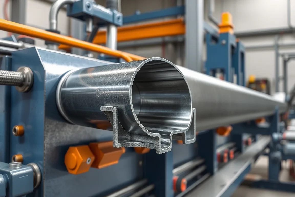
A solar U channel roll forming machine produces an open channel for a specified photovoltaic mounting or support arrangement. The U description identifies a broad shape, not a complete component. Web, flange, opening, holes and material must follow the mounting-system drawing.
The manufacturing question is how that open section meets brackets, posts or other members. A generic U channel may be easy to form but still fail the intended connection because its opening, flange angle or feature pattern is different. The equipment trial should include those interfaces.
What distinguishes the required U channel?
Show web width, flange height, bend radii and any returns. Identify whether the flanges are parallel and how the opening is measured. Include installed orientation and the designated reference end for features.
If the product is called U locally but includes lips or a special edge, draw that explicitly. The tooling should reproduce the actual section rather than a supplier's generic interpretation of the letter shape.
How does it differ from solar C channel?
A C-shaped member commonly includes inward returns or a more closed opening, while the intended U channel may have plain sides. The actual difference must be established from the two drawings. That difference can affect fitting retention, tool access and cutoff support.
If both products are planned, request a separate scope for each. Sharing an application and material does not guarantee that one unchanged set of rolls can make both acceptable sections.
Which mounting interfaces need review?
Provide brackets, bolts, splices or other mating references from the selected system. Show whether components sit inside the channel, on its flanges or against the web. This establishes which dimensions are functional rather than merely overall measurements.
- Internal clearance and contact surfaces.
- Hole and slot locations.
- Connection orientation and fastener access.
- Required end shape or overlap.
- Part identification for the assembly schedule.
Use the intended components in trials. A fit achieved by substituting a smaller bracket is not evidence that the specified channel has been manufactured correctly.
How should features be made and registered?
Define holes and slots from finished-member datums and cut ends. The equipment proposal should explain their position in the punching and forming sequence. Feature access can change after the sides are raised.
Trial actual patterns on representative lengths. Confirm solid end zones and any connection-specific spacing. A plain unpunched sample does not establish normal solar-channel production accuracy or cycle time.
What material and coating information is required?
Specify grade, base-metal thickness and the required corrosion-protection route. The mounting-system application should establish those requirements. Avoid assuming that a generic galvanized description defines the finished product.
Inspect bends and feature edges with production-intent material. Where coating follows fabrication, identify the handoff condition and final inspection responsibility. Preserve batch identity through forming, finishing and packaging.
How should open-channel geometry be checked?
Measure flange angle, opening, web and straightness in the agreed support condition. Do not force the flanges into a fixture that hides their delivered position. Check twist and the relationship between connection faces.
Inspect near the cut ends as well as in the interior. Local opening or closing can occur during cutting or handling and may affect bracket insertion. Record those local effects separately from overall section geometry.
Can sizes change on one production route?
List the actual web, flange, material and feature combinations. Ask which changes use adjustments and which need new rolls, punches or cutting support. Input-strip width and coil changes should be included in the planning matrix.
Demonstrate first-good-member recovery after a relevant transition. Verify the intended bracket or splice fit and feature registration, not only the new outside width. This makes flexibility measurable for the real order mix.
How should similar open channels be separated?
Use clear part references for different flange heights, material grades or slot schedules. The open outline can make variants look deceptively similar in a bundle. Record the approved recipe and maintain member identity through finishing so the assembly team receives the channel specified for that connection, not merely one with a comparable width.
What should acceptance include?
- Confirm the solar-system component drawing and material.
- Measure the relaxed U section and feature positions.
- Inspect cut ends and cable- or hardware-contact edges where relevant.
- Fit intended brackets and connections.
- Check straightness, twist and orientation.
- Verify coating-process scope and bundle identity.
- Record accepted members under normal handling conditions.
The machine trial establishes component manufacture. Wind, snow, foundation and other mounting-system design requirements need their own appropriate engineering and verification.
Frequently asked questions
Can any open channel be used in a solar mounting system?
No. The system requires its specified geometry, material and connections. A generic U outline does not establish compatibility or structural suitability.
Can C-channel tooling simply omit the lips?
That requires a tooling review. The forming sequence, strip development and cutoff support may change. Ask for a defined U-profile arrangement.
Are holes always made before forming?
Not necessarily. The actual process depends on the features and equipment. What matters is that the finished channel meets the approved positions and edge condition.
Why inspect the opening without restraint?
The bracket must fit the delivered part. Clamping the channel into shape can conceal a deviation that appears later during normal assembly.
What should an enquiry contain?
Provide the complete U section, mating parts, material and coating route, holes, lengths and required variants. Add identification and packaging requirements for the actual project workflow.
Define the open section through its mating parts
A useful solar U-channel brief links geometry to bracket fit and feature registration. That helps select a practical forming route while keeping complete mounting-system design separate from the component trial.

Continue your research
- Solar Mounting Roll Forming Machines
- Solar Strut Channel Roll Forming Machine
- Solar Mounting Rail Roll Forming Machine
- Solar C Channel Roll Forming Machine
- Solar Hat Channel Roll Forming Machine
- Solar Purlin Roll Forming Machine
- How Solar roll forming machine Works
- How To Choose a Solar roll forming machine
- Solar roll forming machine Price: What Affects the Cost?
Configuration & specification inputs
Match the configuration to your section drawing, material and production requirements.
| Parameter | Requirement / confirmation needed |
|---|---|
| Profile geometry | Controlled solar U web, flanges, opening, radii and any specified edge modifications. |
| Material | Approved mounting-component steel grade and protection specification. |
| Thickness & grade | Material-thickness combinations reviewed with the actual open section and features. |
| Process route | Coil preparation, registered holes, U forming, cutting and identified finishing or bundling. |
| Cutting | Required lengths with usable open ends and correct project feature registration. |
| Output | Accepted bracket-compatible U members for the stated project schedule. |
| Electrical supply | Utilities for the agreed feature, forming, cutoff and transfer route. |
| Acceptance | Relaxed opening, flange angles, holes, bracket fit, straightness and correct variant identity. |