
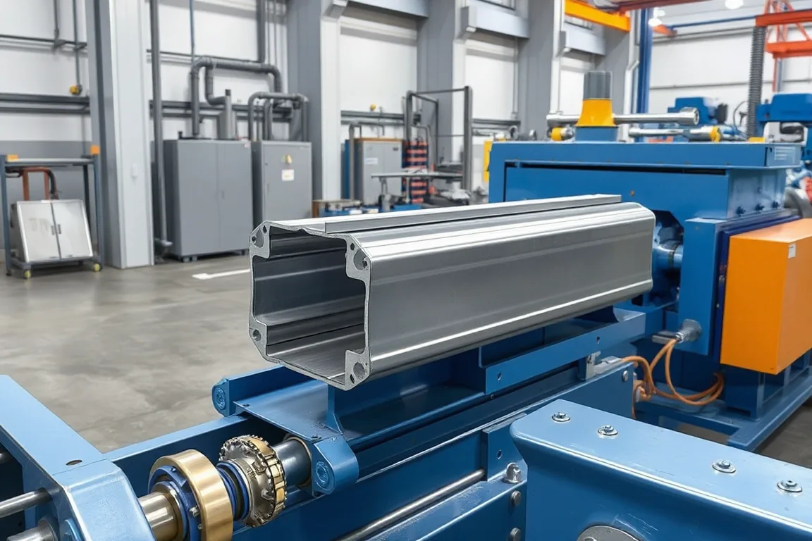
A solar C channel roll forming machine produces a C-shaped steel member for the specified photovoltaic mounting structure. The channel may support modules or connect other structural parts according to the system design. Its section, slots, coating and mating hardware must be defined before the machine is selected.
This is not the same product as an aluminum module frame or every type of solar rail. The C-channel route makes a particular cold-formed member. The equipment should be reviewed against that member's actual role and interfaces rather than the broad solar application label.
Which C-channel geometry is required?
Show web depth, flange widths, lips or returns, bend radii and the channel opening. Identify the installed orientation and the surfaces used to connect brackets or clamps. Some products use plain returns, while others have more specific fitting interfaces.
Include the complete material and coating requirement with the section. A similar outside size does not establish compatibility with another mounting system or its hardware.
How does the member connect to the mounting structure?
Provide the approved bracket, clamp, splice or post-interface drawings. Identify which surfaces carry the hardware and how it is installed. Use representative mating components during the equipment trial.
Do not infer module compatibility from the word solar. The selected system determines the module attachment and structural requirements. The machine's job is to reproduce the controlled member and connection features.
What should the slot and hole schedule contain?
- Hole or slot dimensions and direction.
- Positions from the channel datum and cut ends.
- Repeated and project-specific patterns.
- Required solid areas near connections.
- Part identity and orientation marks.
Define finished-member positions rather than leaving the production team to infer them from a flat sketch. Include actual connection patterns in the trial because feature density can affect both output and registration.
How is the solar channel manufactured?
Coil preparation feeds the agreed punching and progressive forming sequence. The rolls develop the web, flanges and functional returns. Cutting produces ordered lengths, followed by identification and supported bundling.
Ask where features are made relative to forming and how the process preserves their position on the finished section. Any downstream coating, joining or additional fabrication should be listed separately in the route.
How should material and corrosion protection be reviewed?
State steel grade, base-metal thickness and the specified protection system. Precoated strip and coating after fabrication are different arrangements. The final product requirements should establish the route rather than a generic claim about outdoor durability.
Inspect bends, punched edges and connection areas using the actual material. Where coating is applied later, define handoff condition and final-fit inspection responsibilities. Keep material and batch identity through the complete process.
Can one line make several solar C sizes?
Use a matrix of web, flange, lip, material and feature combinations. Some dimensions may adjust while others require different tools. The input width and cutoff support should be included in the review.
Demonstrate changeover through a fully featured member and a connection-fit check. A new web dimension alone does not establish correct clamp or splice engagement. Include the complete first-good-member recovery when comparing proposals.
What should straightness and packaging checks cover?
Measure the relaxed section, straightness and twist on agreed supports. Inspect local end flare and feature condition separately. The channel should not need unplanned reshaping to accept its intended hardware.
Review nesting and bundle restraints with actual members. Protect returns and preserve product identity, especially where similar sizes have different slot patterns. Correctly formed parts still need to arrive in the right order and condition.
How should project patterns remain traceable?
Link each slot program to a controlled member identifier and drawing revision. Similar C channels can have different end connections for different mounting zones, so a shared section name is not enough for sorting. Keep that identity through any coating process and verify bundle labels against the actual feature pattern before delivery.
What should an assembly-oriented trial include?
- Confirm the mounting-system component drawing and material.
- Measure web, flanges, returns and opening.
- Verify holes and cut-to-feature relationships.
- Fit intended clamps, brackets or splices.
- Check straightness and end condition.
- Inspect the required final finish and packaging.
- Record accepted output for a representative order.
Structural loading, wind resistance and corrosion-life claims belong to the complete mounting-system design and assessment. They should not be inferred from a forming demonstration or transferred from another supplier's system.
Frequently asked questions
Is solar C channel the same as a module frame?
No. A module frame and a mounting-structure channel serve different roles and may use different materials and manufacturing processes. Specify the actual component required.
Will any solar clamp fit?
Do not assume compatibility. Provide the intended clamp or bracket and verify the channel interface using its controlled drawing and sample.
Can slot positions change for different projects?
Only to approved component schedules within the equipment scope. Keep pattern identity and revision control so similar channels are not mixed.
Does the line include outdoor coating?
Only the specified route is included. State whether the input is precoated or whether a separate post-fabrication process completes the product.
What should be provided for quotation?
Send section and connection drawings, material and coating requirements, slot patterns, lengths and the size matrix. Add the expected order mix and required identification method.
Connect channel production to the actual mounting interface
A solar C-channel proposal is strongest when forming, features and final hardware fit are reviewed together. That produces a practical equipment scope without confusing component manufacture with complete system design.

Continue your research
- Solar Mounting Roll Forming Machines
- Solar Strut Channel Roll Forming Machine
- Solar Mounting Rail Roll Forming Machine
- Solar U Channel Roll Forming Machine
- Solar Hat Channel Roll Forming Machine
- Solar Purlin Roll Forming Machine
- How Solar roll forming machine Works
- How To Choose a Solar roll forming machine
- Solar roll forming machine Price: What Affects the Cost?
Configuration & specification inputs
Match the configuration to your section drawing, material and production requirements.
| Parameter | Requirement / confirmation needed |
|---|---|
| Profile geometry | Approved solar C-member web, flanges, returns, opening and installed orientation. |
| Material | Mounting-system steel grade and specified corrosion-protection route. |
| Thickness & grade | Section-specific grade and base-metal thickness combinations with traceable input. |
| Process route | Registered project features, C forming, length cutting, identification and defined finishing handoff. |
| Cutting | Member lengths preserving connection zones and controlled hole-to-end relationships. |
| Output | Accepted identified C members under the actual mounting-pattern and size mix. |
| Electrical supply | Utilities for punching, forming, cutoff and selected handling equipment. |
| Acceptance | Section, slots, intended clamps or brackets, splice fit, straightness and final-condition identity. |