
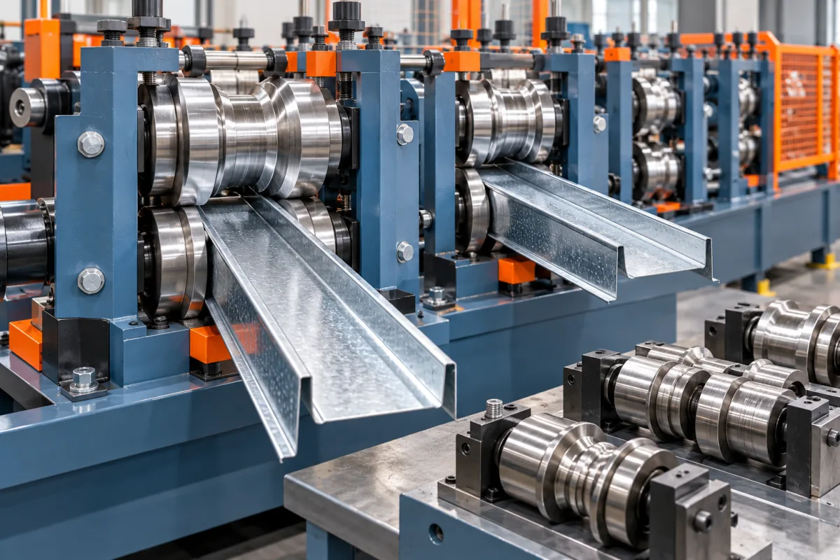
Stud and track tooling should be reviewed as a system that produces compatible framing sections. The stud's web, flanges and lips must meet its drawing, while the track must provide the specified receiving geometry. The complete pair is a more meaningful acceptance target than two isolated channel samples.
Start with actual dimensions, not trade names
Provide controlled drawings for both members, including bends, lips and relevant feature references. A shared nominal size does not mean the actual dimensions should be identical. The intended fit must be defined by the framing product, not improvised at commissioning.
Identify which dimensions govern assembly and how they are measured. If the inspection datum differs between supplier and buyer, both may report acceptable dimensions while evaluating different relationships. Resolve that ambiguity before tools are approved.
Review development of the lips and flanges
The section is formed progressively from strip. The tooling sequence must account for the full geometry and approved material. Ask the designer to explain the important features and the evidence used to support the requested range.
Do not treat roll count as a quality ranking. A tool arrangement is useful when it repeatedly delivers the specified section and fit. Different design concepts may use different configurations to achieve that result.
Define what can adjust and what needs new parts
Web-width flexibility does not automatically imply unlimited flange, lip or track geometry. Request a matrix of supported combinations and the components required for each. Distinguish changes within one product family from a new section design.
For stud-to-track conversion, identify the complete sequence, including guides, feature settings, cutting parts and first-off checks. The phrase combination line is not enough to describe how the product is recovered.
Coordinate service-hole and forming references
Where holes or slots are included, their final position must agree with the member drawing. The feature-making stage and forming tools therefore need a shared reference scheme. A clean hole in flat strip does not prove correct location in the finished stud.
Confirm which patterns the proposed equipment can make and what additional tools are required. Any change to a feature should follow the approved product design rather than being chosen solely because it is convenient for the punch arrangement.
Include specified embossing or surface features
If the product drawing includes embossing or another repeated feature, identify its intended geometry and production stage. It is part of the tool scope, not a generic decorative option. The trial should use the actual material and inspect the final section.
Do not infer structural or fastening performance from the presence of a visible pattern alone. The tooling review establishes manufacturing capability for the specified feature; the framing system's required performance needs its own evidence.
Match tools to the material matrix
Grade, thickness convention, coating and developed strip width should be provided for every required combination. The tooling must be evaluated with those materials rather than a single convenient demonstration coil.
Material changes can affect the final section and mating fit. Retain the coil identity with samples and setup references. A tool set approved for one drywall product should not automatically be described as validated for a different structural member.
Check cut ends and packaging behavior
The cutting route must leave usable ends without unacceptable deformation. Inspect complete members, not only central coupons. If a stud fits the track in the middle but a distorted end prevents assembly, the production route has not met the requirement.
Where nesting or automated bundling is planned, demonstrate it with the required sections. Tooling and downstream handling interact through the product geometry. A small dimensional change can affect packing even when an isolated member seems acceptable.
Validate a return to the original pair
Include the downstream packaging condition in that recovery test if nesting or counting depends on the section. A member can remain within one measured dimension while another feature affects how it collects. Record whether the restored setup delivers the intended bundle without local reshaping or manual sorting beyond the agreed route. This is especially informative when a line changes frequently between studs and tracks, because product recovery should include the interfaces used during normal commercial production, not only a favorable inspection sample taken directly from the mill.
A flexible line should demonstrate a relevant size or product change and recovery of a previously accepted configuration. Inspect both members of the pair after return. This tests whether setup records support repeatable production rather than a one-time sample.
- Identify the initial stud and track drawings.
- Produce and measure the approved pair.
- Perform the required product or size transition.
- Approve the second configuration and its features.
- Return to the original setup and repeat fit checks.
Control future geometry changes across the pair
A revised stud flange or lip can affect mating track requirements and material development. Review the pair and its intended assembly before changing only one tool dimension. Keep drawings, tool identities and setup references aligned.
For example, changing the actual stud envelope while retaining the old track tooling may create interference even though both retain the same trade size. A practical change review asks which dimensions and components are affected, what material width is needed and which assembly checks must be repeated.
Frequently asked framing tooling questions
Can one web-width setting define the whole stud?
No. Flanges, lips, bends and features also define the member. Use the complete section and material combination.
Why test the track when only stud tools changed?
The stud is part of a mating system. A local change can affect fit with the existing track, so the pair should be checked under the approved assembly criteria.
Does visible embossing prove a stronger framing product?
No. Its manufacturing and performance roles need to follow the approved design and evidence. A surface pattern alone is not a rating.
What records make tooling service easier?
Controlled pair drawings, tool identification, supported materials, setup references and acceptance results including fit and cut ends. Those records let the team recover the correct product rather than rely on an unlabelled sample.
Continue your research
- Stud & Track Roll Forming Machines
- Drywall Stud Roll Forming Machine
- Drywall Track Roll Forming Machine
- C89 Light Gauge Steel Framing Machine
- C140 Light Gauge Steel Framing Machine
- Top Hat Light Steel Framing Machine
- How Stud and track roll forming machine Works
- How To Choose a Stud and track roll forming machine
- Stud and track roll forming machine Price: What Affects the Cost?