
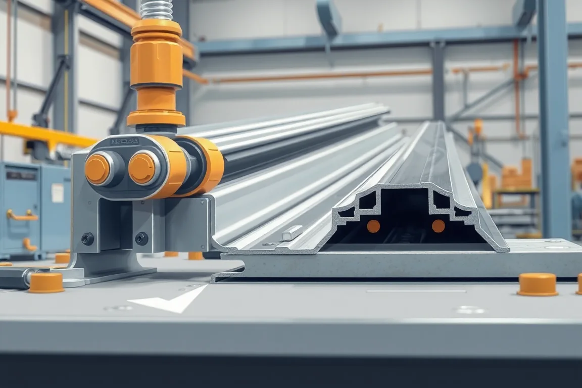
Maintenance for a ceiling-profile line should preserve small functional features, thin-section geometry and any exposed decorative face. A simple furring-channel route and a capped grid-runner route need different task lists. The plan must follow the actual material feeds, forming, features, joining, cutting and packing equipment.
Map the assets in the chosen construction route
Identify every machine and auxiliary unit, including cap feeds or connector equipment where used. Assign ownership and use each manufacturer's maintenance instructions. Do not apply a channel-only checklist to a multi-operation grid line without reviewing the missing assets.
Record the component configurations served by each unit. This helps connect a service event with later fit or appearance observations. A generic entry that the ceiling line was checked provides little evidence when several products share equipment.
Keep isolation and qualified work explicit
Use the approved shutdown, isolation and access procedures for inspection, cleaning and service. Forming rolls, feature tools and feed systems create hazards even when the components they produce are small. Slow motion is not a safe maintenance condition.
Operators should report abnormal behavior from permitted positions and escalate defective guarding or other unsafe conditions. Qualified personnel should control investigation and equipment release. The checklist should not encourage improvised access to maintain output.
Inspect each strip-feed path
For single-strip profiles, review payoff and entry equipment under their instructions. For a construction with a separate cap, include that feed and its references. Record damage, contamination or wear that could affect material presentation.
Keep material orientation and width references legible. A cap or body-feed mix-up can create product defects even when the equipment is mechanically sound. Maintenance should preserve the information needed for correct setup.
Protect small forming and bearing features
Service tools according to their approved procedures and maintain correct component identification. Small returns and bearing surfaces may be functionally important. Similar-looking tools from another profile should not be substituted without confirmation.
Record work that could affect section geometry and specify the required product checks afterward. A cleaned or replaced tool should be evaluated through its output, not only by visual inspection of the component itself.
Maintain cap and joining equipment where fitted
Follow the documentation for the actual joining or capping method. Inspect the relevant alignment and contact components under safe isolation and record findings. The task list should distinguish a visible-face issue from a body-section issue.
After service, inspect complete runners for the specified cap relationship and finish. A mechanically successful cycle does not prove that the decorative face remains acceptable through subsequent cutting and packing.
Control punches and connector tools
Slots, hanger holes and end-connector details require verified tool identity and condition. Maintain associated scrap arrangements according to the maker's instructions. Keep each tool connected to its component drawing and revision.
Release work with feature-position and mating checks on the final component. A clean punch impression alone does not establish a correct cross connection. Use the specified receiving and mating parts.
Inspect cutoff and collection supports
Cutting equipment must preserve the relevant end details and thin flanges. Confirm correct tools and supports for the product configuration. Record local deformation separately from length error.
Maintain the downstream contact surfaces that collect and package components. A damaged support can bend a return or mark a cap after successful forming. Include the normal handling boundary in the product-release check.
Keep data, counts and reference samples controlled
Follow the supplied process for approved control settings and authorized changes. Feature patterns, component lengths and identification need verification after relevant control work. A functioning display or communication link is not proof of correct production data.
Maintain measuring equipment and identifiable reference assemblies. A bent or unlabelled sample can become a misleading master. Keep the component, connector and material revisions associated with each acceptance reference.
Release service through a component assembly
Select checks proportionate to the work and retain normal first-off requirements. Inspect the continuous section, features, end condition and visible face, then assemble the specified interface. Include package count and identification where the serviced equipment affects them.
- Confirm component and material-stream identities.
- Complete required equipment safety and service release.
- Produce identified representative components.
- Measure section and feature references.
- Check connectors or hanger fit with approved mates.
- Inspect after collection and record release.
For example, replacing a cap-feed contact component may remove a scratch without proving connector spacing. Verify the affected finish and retain the normal feature checks. Work on an end-punch station requires a different focused verification, including engagement with the receiving runner. This keeps service release tied to actual product risk.
Use recurrence to improve the checklist
Revise the release sample when the product catalog changes. Adding a capped runner or a new connector can introduce an interface that the old plain-channel sample never exercises. The maintenance plan should state which representative components verify the current route after relevant service, so an unusual customer order does not become the first real test of recovery.
Link service findings with connector rejects, cap damage, section deformation and count errors. Investigate repeated conditions before adding generic tasks. A recurring defect may indicate an upstream contamination source or a handling problem rather than insufficient maintenance of the first suspected tool.
Review spares against the current component catalog. Identify obsolete connector revisions and tools clearly. A replacement part is useful only when its correct application and post-service checks are known.
Frequently asked ceiling-line maintenance questions
Can a channel maintenance plan cover capped T-grid equipment?
Only after adding the actual cap, joining and connector assets and their instructions. The construction determines the task list.
Why maintain reference assembly samples?
They help verify functional fit, but only when their identities and condition are controlled. Damaged or mixed samples can mislead production decisions.
Should connector tools be identified by appearance?
No. Use verified part references and component revisions. Small differences can affect engagement with mating members.
What confirms return to normal production?
The required equipment release and accepted representative components through their relevant assembly and handling checks. Successful machine movement alone does not establish the finished ceiling member.
Continue your research
- Ceiling & Furring Roll Forming Machines
- Furring Channel Roll Forming Machine
- Main Channel Roll Forming Machine
- Hat Furring Channel Roll Forming Machine
- Ceiling Carrying Channel Roll Forming Machine
- Ceiling T Main Runner Roll Forming Machine
- How Ceiling roll forming machine Works
- How To Choose a Ceiling roll forming machine
- Ceiling roll forming machine Price: What Affects the Cost?