
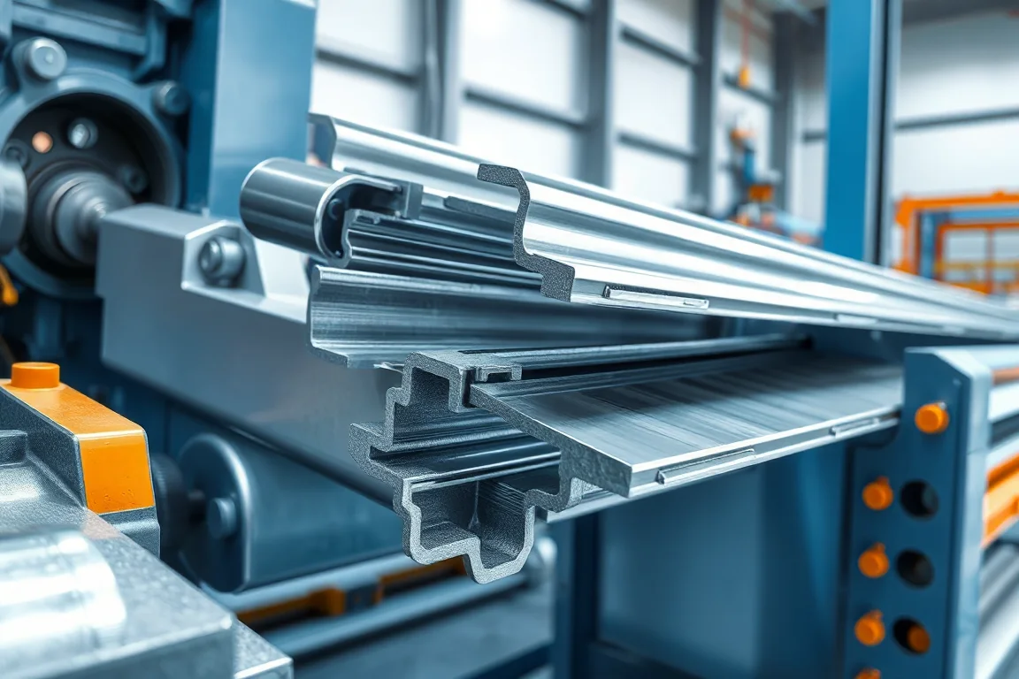
Storage rack uprights and beams are not generic channels. Their function depends on a coordinated set of dimensions: the upright section, the connector-hole pattern, the beam mating geometry and any shelf returns. A storage rack roll forming machine roller tooling design is the engineering work that turns those functional dimensions into a sequence of forming, punching and cutting operations. The quality of that design shows up in hole position repeatability, section straightness, connector engagement and the ability to reproduce the same part after a tool change.
This guide answers the design question directly: what should be decided about rollers, punches and cutoff tooling, in what order, and how can a buyer assess a proposed design without treating a roll count or a model label as proof of capability. It is an editorial framework, not a specification for any particular machine.
Start from functional geometry, not from a machine model
Roll tooling exists to produce a component that mates with other components. For an upright, the critical features usually include the overall section shape, the position and size of connector holes, the surfaces that engage beam connectors and any return flanges or shelf supports. For a beam, the critical features include the mating geometry that locks into the upright connector and, in the case of a built-up box beam, the interfaces between the formed sections that will later be joined.
Before discussing roll stands, the design should identify which dimensions are functional and which are incidental. Functional dimensions are the ones that affect assembly, load transfer or connector fit. Incidental dimensions can vary within a tolerance without affecting the rack. Hole pattern datums are especially important: the position of a hole relative to a bend, an edge or another hole may matter more than the overall channel width. If the design starts from a nominal profile drawing without defining datums and mating parts, later tooling decisions have no fixed target.
How the forming sequence develops from strip to section
A roll forming line develops the section progressively. Each pass bends the strip a controlled amount, and the sequence of bends determines whether the strip can be formed without buckling, twisting or marking. The design should describe the order in which bends are introduced, which surfaces locate the strip in each pass, and how the strip is supported as the section closes.
The sequence is not simply a series of identical stations. Early passes typically establish a reference edge or a shallow bend that helps guide the strip. Later passes bring the section to its final geometry. The design must account for springback, the tendency of steel to recover some of its bend angle after the rolls release it. Springback is managed by overbending, by adjusting roll gaps or by a combination of both, but the method must suit the material and the section. Access to the final section is also a design consideration: if the tools crowd the section, it may be difficult to adjust or maintain without disturbing other settings.
The forming sequence interfaces with punching and cutting. If holes are punched before forming, the tooling must allow for the way the strip moves and stretches during bending. If holes are punched after forming, the punch tooling must reach the formed section without distortion. The cutoff follows the forming and punching operations and must produce a clean end without collapsing the section. These interfaces are part of the roller tooling design, even when they are handled by separate units.
Punch and cutoff tooling as part of the same design
Punch tooling defines the hole pattern. The design should specify each hole type and its datum: connector holes, mounting holes, slotted holes and any special features. The punch unit must be able to produce those holes repeatedly at the line speed the buyer intends to use. The acceptance criteria for holes include position relative to the datum, diameter or slot size, edge condition and absence of distortion around the hole.
Cutoff tooling defines the end of the part. The cutoff must match the profile so that the cut does not crush or twist the section. For uprights and beams, the cut length and end squareness affect assembly. If secondary operations are needed, such as notching or end forming, the design should state whether they are performed in line or separately. The key point is that punch and cutoff tooling are not accessories to be chosen after the rolls; they are part of the same forming system and should be reviewed together.
Tool changeover and the limits of a single setup
Storage rack manufacturers often produce more than one upright size or connector pattern. The roller tooling design should address how tool changes are made and whether the same line can run different profiles. A tool change may involve changing rolls, adjusting spacers, repositioning punch units or altering the cutoff. The design should identify which parts are dedicated to a profile and which are shared.
Changeover capability should be demonstrated with the intended products. A design that works for one upright may not work for another with a different hole pattern or a different bend radius. The buyer can ask for a changeover sequence that uses the agreed material and the profile extremes, and can request that the accepted setup and tool identification be documented. The goal is to avoid production depending on an undocumented adjustment that only one operator knows.
Material variation, springback and forming limits
Structural steel varies in yield strength, thickness and surface condition. The roller tooling design cannot assume a single set of properties. The design should explain how it accommodates material variation: which adjustments are available, how springback is compensated and what the forming limits are for the specified material. A design that relies on a narrow band of material properties is more likely to produce inconsistent parts when the steel changes.
Thickness variation affects bend radius, springback and hole position. The tooling should be able to maintain the functional dimensions across the thickness range the buyer intends to run. This is not a claim that any range is acceptable; it is a design question. The supplier should be able to explain how the tools behave at the thin and thick ends of the range and what adjustments are needed.
Why a roll count alone does not demonstrate quality
A common way to compare machines is by the number of roll stands. A higher roll count can allow more gradual bends and finer control, but it does not by itself guarantee a better section. The quality comes from the forming design: how the bends are distributed, how the strip is located, how springback is managed and how the tools are made and set. A machine with many rolls but a poor forming sequence can still produce twisted or wavy sections. A machine with fewer rolls and a well-designed sequence can produce acceptable parts for a given profile.
When evaluating a proposal, ask for the forming design rather than the roll count. The design should show the bend progression, the locating surfaces and the adjustment provisions. It should also explain how the final section is accessed for maintenance and how the tooling is identified.
Component production versus assembly and certification
Roll forming produces components: uprights, beams and possibly other parts. It does not produce a finished rack system. Assembly, connector attachment, welding of built-up beams and any coating or finishing are separate operations. Rack load capacity must be established for the finished racking design, not for the formed component alone. A former does not automatically include welding, connector attachment or rack-system approval. This distinction matters because a tooling design that produces a good section can still be part of a rack that fails if the assembly or the system design is inadequate.
The buyer should keep component acceptance separate from system approval. Component acceptance verifies that the formed part matches the agreed drawing and that the interfaces are correct. System approval involves the finished racking design and its load capacity, which is outside the scope of the roll forming machine.
Practical acceptance checks for tooling and formed parts
Acceptance should be based on the agreed component drawing and the intended interfaces. A practical set of checks includes:
- Test beam connector engagement with the upright. The connector should enter and lock without forcing or excessive play.
- Inspect repeated holes for position, size and edge condition. Compare them to the datum defined in the drawing.
- Measure section straightness and twist. A straight section helps assembly and load transfer.
- Check cut length and end quality. The cutoff should not crush or distort the section.
- For built-up box beams, include the joining operation and its quality checks in the acceptance plan.
- Verify that tool changes can be made using the agreed material and profile extremes, and that the accepted setup is documented.
These checks are evidence. They should be performed on the actual profile and material, not on a demonstration part that is not representative.
Comparison of tooling design alternatives
Two broad approaches are common. A dedicated tooling set is designed for one profile or a narrow family. It can achieve good repeatability and simpler changeover, but it limits flexibility. A flexible tooling set with adjustable rolls and punch units can run multiple profiles, but it may require more setup skill and may have more adjustment points that can drift. The trade-off is between changeover speed, repeatability and the range of profiles.
Another choice is between punching before forming and punching after forming. Punching before forming can allow a simpler punch unit, but the hole position may shift during bending. Punching after forming can place holes more accurately in the finished section, but the punch tooling must reach the formed section without distortion. The right choice depends on the hole pattern, the material and the acceptable tolerance. There is no universal answer; the design should explain the reasoning for the chosen sequence.
Cost scope and accepted-output cost
When comparing costs, define the scope of the quote. Does it include the forming rolls, punch tooling, cutoff tooling, changeover parts, documentation and acceptance tests? Does it include training or installation? A lower price for the rolls alone may not reflect the total cost of a working tooling system. Accepted-output cost is the cost per acceptable part produced by the line. It includes the tooling, the setup time, the scrap rate, the maintenance and the changeover time. A tooling design that produces parts faster but with more scrap or more frequent adjustment may have a higher accepted-output cost. Because prices and rates vary, the buyer should request a breakdown of scope and use their own production assumptions to compare alternatives.
Documentation and tool identification
The design should leave a record. Tool identification, accepted settings, adjustment ranges and changeover procedures should be documented and kept with the tooling. This reduces dependence on individual operators and helps maintain consistency over time. The documentation should also include the agreed component drawing and the acceptance criteria. Without this record, a successful setup can be lost when the line is moved or when personnel change.
FAQ
What is the most important dimension in an upright profile?
The most important dimension is usually the one that controls connector fit and hole position relative to the mating surfaces. Overall channel width may be less critical than the relationship between the hole pattern and the surfaces that engage the beam connector. The drawing should define datums and functional dimensions so that tooling can target them.
How do I evaluate a proposed forming sequence?
Ask for the bend progression, the locating surfaces and the springback compensation method. A good proposal explains how the strip is guided, how the section is closed and how the final shape is accessed. It should also show how the sequence changes for different profiles or materials.
Can the same tooling run different upright sizes?
It depends on the design. Some tooling sets are dedicated to one profile, while others allow adjustments or roll changes for a family of profiles. The changeover should be demonstrated with the intended products, and the limits of the adjustment should be documented. A claim of flexibility without a demonstration is not sufficient.
When should holes be punched, before or after forming?
Punching before forming can simplify the punch unit but may allow hole position to shift during bending. Punching after forming can place holes more accurately but requires tooling that reaches the formed section without distortion. The decision should be based on the hole pattern, material and tolerance requirements, and the design should explain the trade-off.
How do I verify that the tooling will produce acceptable parts?
Acceptance should include connector engagement, hole inspection, straightness measurement and cut end quality. These checks should be performed on the actual material and profile. For built-up beams, the joining operation and its quality checks should also be included. The results should be compared to the agreed component drawing.
What does a roll forming machine not include?
A roll forming machine does not automatically include welding, connector attachment, coating or rack-system approval. It produces formed components. Assembly, finishing and load capacity verification for the finished racking design are separate activities. The buyer should keep these scopes distinct when planning production.
Continue your research
- Storage Rack & Shelving Roll Forming Machines
- Rack Upright Roll Forming Machine
- Pallet Rack Beam Roll Forming Machine
- Teardrop Rack Upright Roll Forming Machine
- Pallet Rack Box Beam Roll Forming Machine
- Pallet Rack Step Beam Roll Forming Machine
- How Storage rack roll forming machine Works
- How To Choose a Storage rack roll forming machine
- Storage rack roll forming machine Price: What Affects the Cost?