
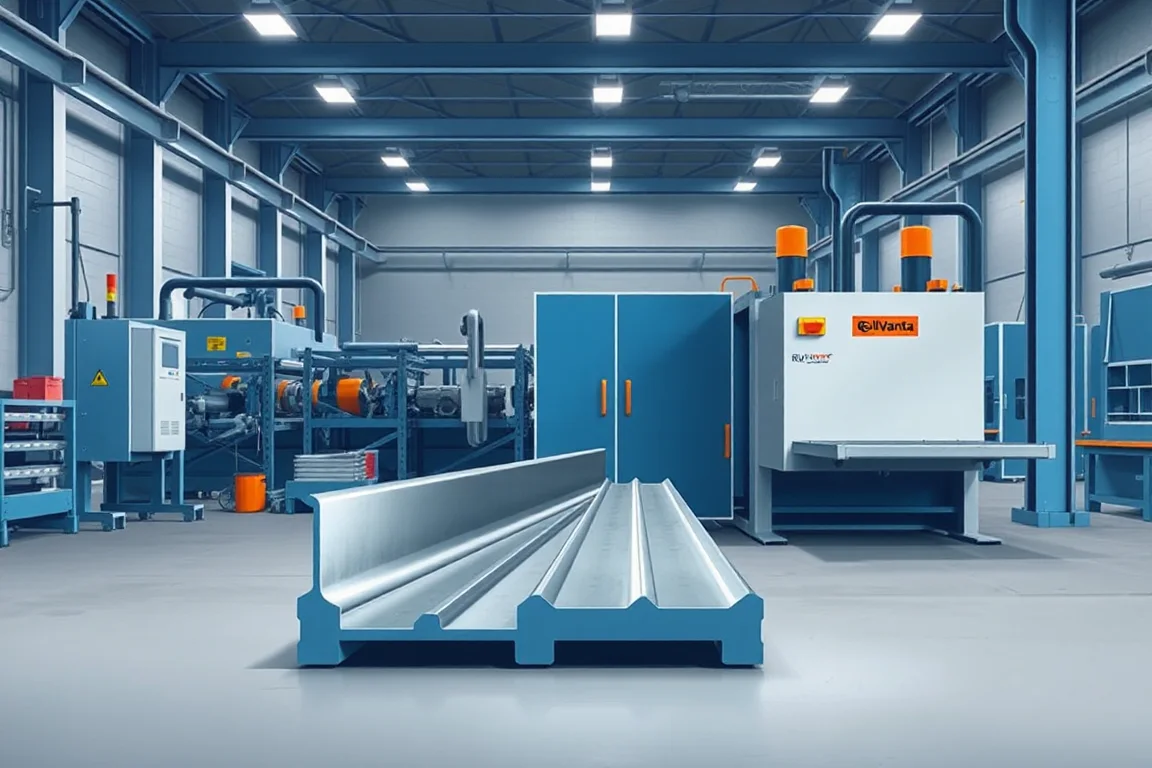
A pallet rack beam roll forming machine produces the longitudinal sections used to build the horizontal beams of a specified storage-rack system. The complete beam also includes its joining construction, end connectors and finishing. Those elements determine how a formed profile becomes an accepted rack component.
Beam designs vary. A step beam, a box-type member assembled from formed parts and another closed construction can require different tools and secondary operations. The equipment enquiry should identify the exact product rather than treating every rectangular-looking beam as the same manufacturing task.
Which beam construction is intended?
Start with the complete cross-section and assembly drawing. Identify whether the member uses one formed strip, nested or paired sections, and any seam or other joining operation. Show the load-supporting step or surface where it exists.
The chosen construction determines the production boundary. A former making one half of a beam is not a complete beam line unless mating-part production, joining and end-connector attachment are also covered. List each stage explicitly.
What should the drawing package include?
- Main beam section and any separate mating section.
- Step geometry or pallet-supporting surface.
- Seam, nesting or joining details.
- End connectors and their orientation.
- Material grade, thickness, finish and length range.
- Required inspection references for the completed beam.
Provide the intended upright interface and locking components where applicable. End-connector fit is a system-specific relationship and should not be inferred from a generic rack-beam illustration.
How does roll forming fit into beam manufacture?
The forming route develops the specified longitudinal section from coil and produces the required lengths or continuous section for downstream work. Feature-making and joining can be integrated or separate according to the selected construction.
- Identify the material and released beam configuration.
- Guide the strip and produce required features.
- Develop the section, including steps, returns or seam preparation.
- Complete the specified longitudinal joining or mating operation.
- Cut or prepare the required beam length and ends.
- Attach end connectors through the approved process.
- Inspect, finish and identify the complete beam.
The actual sequence can vary. Compare the proposed route against the product drawing and identify any manual or subcontracted stages rather than assuming the word automatic covers the whole beam.
What matters about step-beam geometry?
A step can provide the defined seating relationship for decking or other rack components. Its depth, width and position must match the product design. The broad outside beam dimensions do not fully describe this interface.
Use the intended support components during trials. Check that they seat as specified without local modification and that the beam ends do not obstruct the arrangement. A successful loose fit is a manufacturing observation, not a substitute for the rack's structural verification.
Where the same beam family includes several heights or steps, list those changes separately. An adjustment that changes overall depth may not preserve the correct step or seam geometry automatically.
How should closed or nested beam constructions be reviewed?
Identify how the formed elements meet and how the joint is made. The mating relationship, overlap or seam condition must be controlled before joining. A profile that looks closed from outside can still have an incorrect internal fit or joint preparation.
Inspect both the formed components and the completed member. Joining can introduce distortion or change dimensions, so a good pre-joining section is not the final acceptance result. Use the approved process and inspection plan for the selected beam construction.
If multiple component streams feed assembly, balance their output and identification. Producing extra outer sections does not complete beams when the required inner or mating parts are missing.
How should material combinations be specified?
List grade, thickness, strip width and surface condition for every beam component. Similar external beam sizes may use different materials in the rack catalogue, so the production system must distinguish them reliably.
Trial the actual material combinations and record them with section and joining measurements. Material response affects bends, springback and the condition presented to the joining operation. Do not assume that one convenient stock demonstrates every required variant.
Keep material identity linked through end-connector attachment and finishing. This supports later quality investigation and prevents visually identical beams from different specifications being mixed in dispatch.
Why do end connectors need their own fixture review?
The connectors establish the beam's relationship with the uprights. Their orientation, height and distance apart are functional dimensions of the completed member. A correct main profile cannot compensate for an incorrectly positioned connector.
Define the locating fixture and joining procedure, then inspect the completed beam with the intended upright references. Check both ends and any locking arrangement. Record unplanned force or local correction instead of accepting an assembly that only fits after modification.
Connector attachment and connection performance need their applicable engineering and quality controls. The roll former's dimensional trial should not be presented as verification of the complete connection's load behavior.
What does a beam-size change involve?
Separate length changes, section-height changes, step changes and connector changes. They may affect different tools and fixtures. Request a matrix covering rolls, guides, cutoff parts, joining settings and end-connector location.
Demonstrate a representative transition through to an accepted complete beam, then recover the original product. Include setup scrap and final inspection in the first-good-product time. A quick forming adjustment alone does not establish the turnaround of the entire route.
If a shared line produces several beam constructions, review their scheduling and component-storage needs. The most flexible former may still rely on dedicated joining or end fixtures for particular products.
How should straightness and final alignment be checked?
Measure the beam under agreed support conditions after all included joining operations. Distinguish twist, bow, local end distortion and connector misalignment. Each can originate at a different stage of the route.
Compare before-and-after measurements when investigating a change. A deviation introduced by connector attachment should not automatically lead to an adjustment of the main roll tools. Retain accepted component and finished-beam references to support that distinction.
What handling and finishing details matter?
Protect end connectors and support surfaces during movement and packing. Define bundle orientation so hooked or projecting components do not damage neighboring beams. Inspect representative parts after normal handling.
Coordinate the finishing route with final connector fit and identification. Labels should distinguish section, material, length and product reference, even where finished colors are identical. Setup pieces and unfinished blanks should remain separate from accepted beams.
How should output and investment be compared?
Use accepted complete beams for a stated construction and length mix. Section forming, mating-part production, joining, end attachment and finishing can each constrain the result. An isolated strip speed does not describe the dispatch-ready beam rate.
For planning only, 400 beams with two end connectors require 800 accepted connectors plus the correct beam bodies and joining work. This component balance helps evaluate the production route; it does not define a rack design or capacity.
Compare quotations with equivalent joining, fixtures, inspection and handling scope. Identify product qualification responsibilities separately. A bare profile former and a complete beam-manufacturing system should not be judged as if they deliver the same output.
What should acceptance include?
- Section and step geometry in the approved material.
- Mating or seam condition and the required joining checks.
- Finished length and end-connector positions.
- Straightness and twist after complete fabrication.
- Fit with intended uprights and support components.
- Required size changes and recovered production.
- Final finish, labels and packed-beam condition.
Retain the settings and samples for both formed components and completed beams. They make repeat production and later investigations more reliable.
Frequently asked questions
Are all box beams made from one strip?
No. Construction can involve different formed elements or joining arrangements. Supply the complete section and assembly drawing so the equipment route matches the intended product.
Does the former attach beam connectors?
Only if that operation and its fixtures are explicitly included. End-connector attachment is a separate functional stage and must be checked on the completed beam.
Can step geometry change automatically?
Only within the supported tooling configuration. A new step or seam can require different tools even when the outside beam height is similar. Review the actual size matrix and demonstrate the transitions.
Why measure after joining?
Joining can change alignment and dimensions. Correct formed parts do not automatically guarantee a correct complete beam. Final measurements help distinguish forming deviations from later fabrication effects.
Does accurate beam production establish rack capacity?
No. Capacity depends on the complete rack design, connectors, configuration and required evidence. Machine acceptance verifies manufacture of the specified beam rather than assigning a universal load rating.
What should be sent for a quotation?
Provide beam and connector drawings, construction method, materials, lengths, finish and expected order mix. Add support-interface and inspection requirements. This defines the complete production scope.

Continue your research
- Storage Rack & Shelving Roll Forming Machines
- Rack Upright Roll Forming Machine
- Shelf Panel Roll Forming Machine
- Teardrop Rack Upright Roll Forming Machine
- Pallet Rack Box Beam Roll Forming Machine
- Pallet Rack Step Beam Roll Forming Machine
- How Storage rack roll forming machine Works
- How To Choose a Storage rack roll forming machine
- Storage rack roll forming machine Price: What Affects the Cost?
Configuration & specification inputs
Match the configuration to your section drawing, material and production requirements.
| Parameter | Requirement / confirmation needed |
|---|---|
| Profile geometry | Controlled beam body, step or mating section and end-connector arrangement |
| Material | Component-specific grade and thickness linked through joining and finishing |
| Thickness & grade | Review every beam-body and mating-part material combination |
| Process route | Section forming, specified longitudinal joining, end preparation, connector attachment and final inspection |
| Cutting | Coordinate body length and end preparation with completed connector spacing |
| Output | Accepted fabricated beams with joining and end-connector work included |
| Electrical supply | Confirm forming, joining, cutting, fixture and handling utility requirements |
| Acceptance | Check section and joints, final straightness and connector positions, then fit intended uprights |