
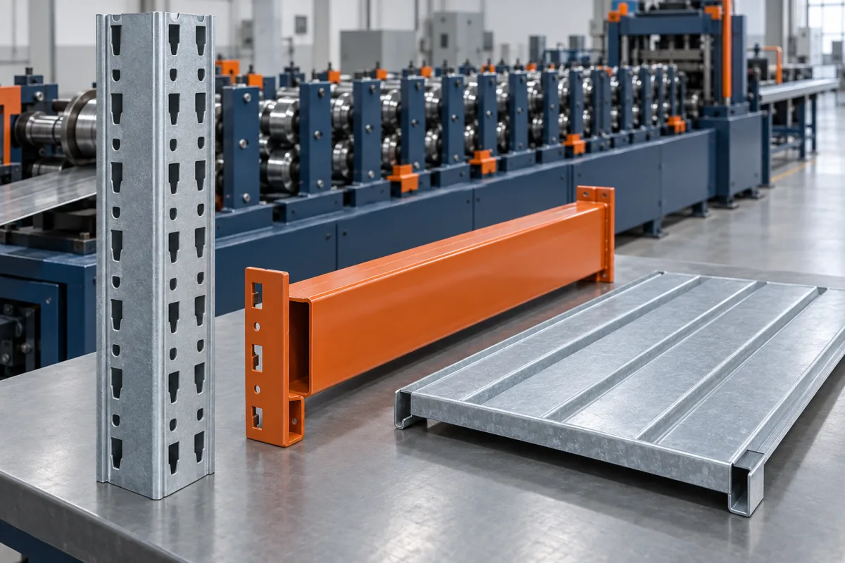
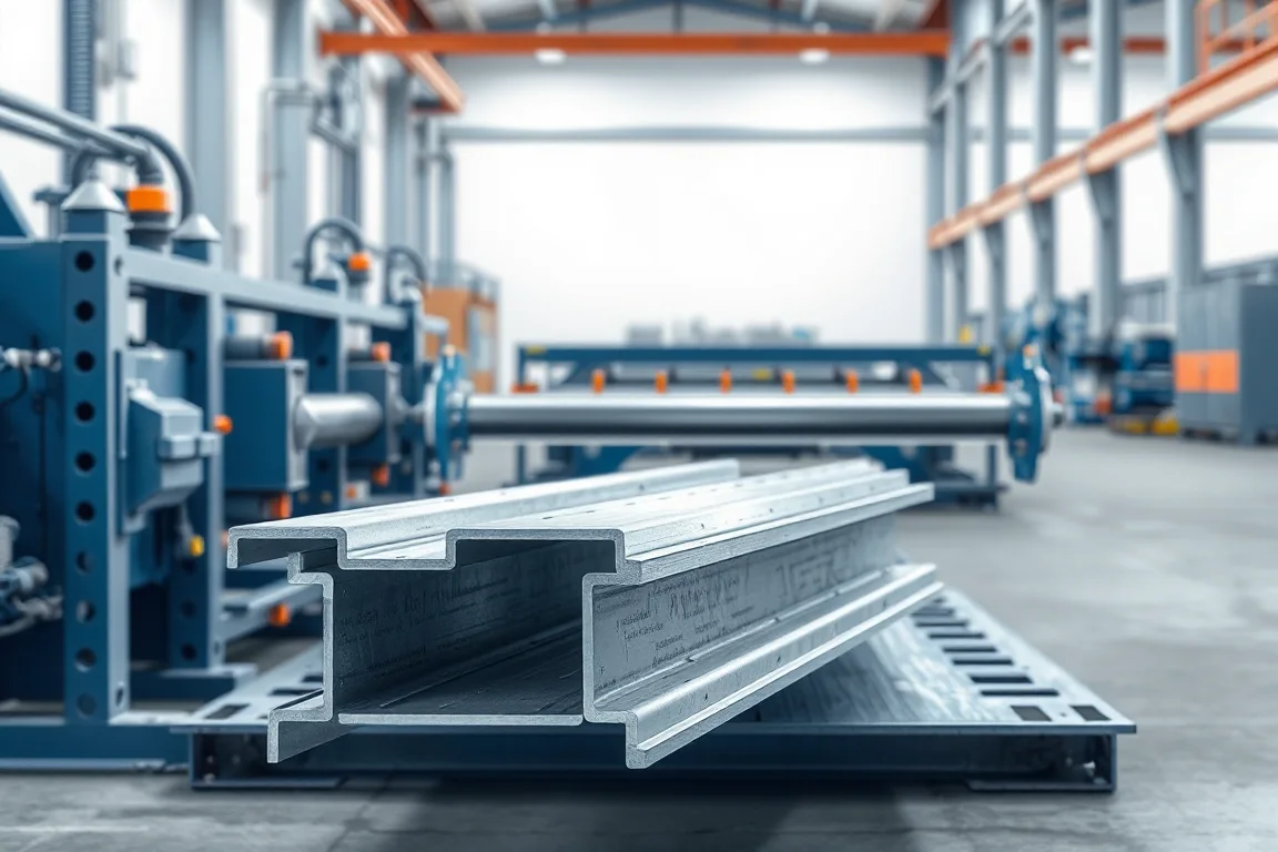
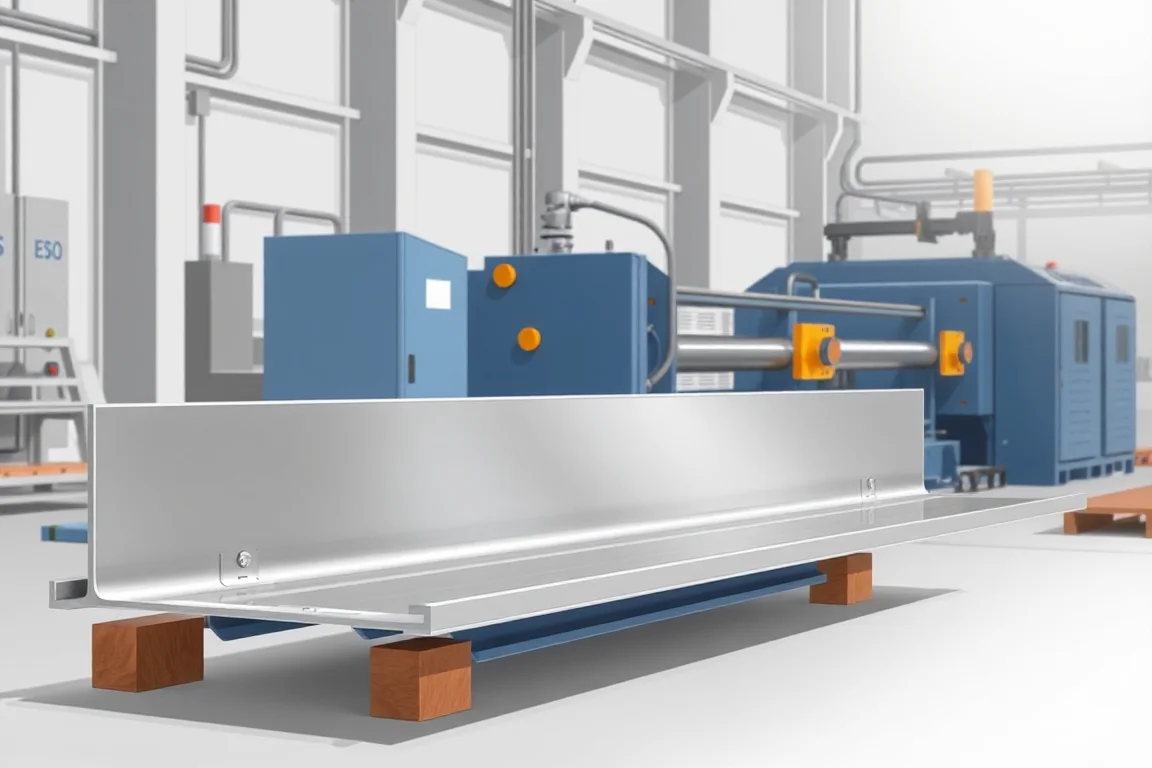
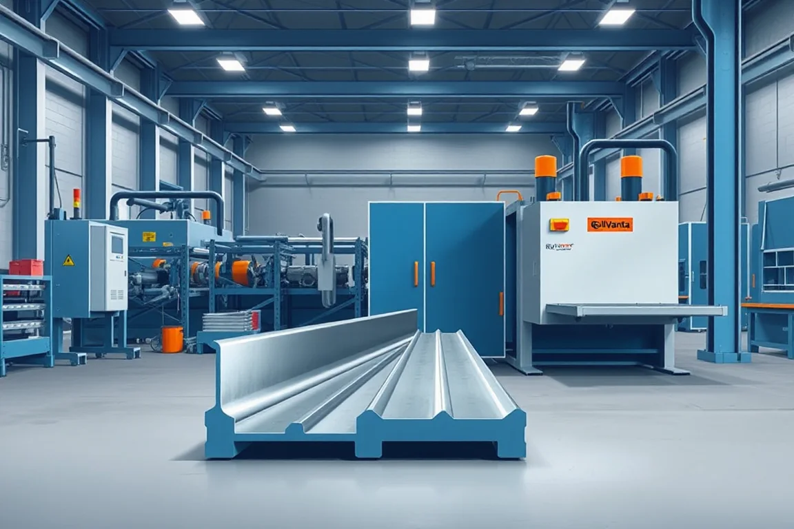
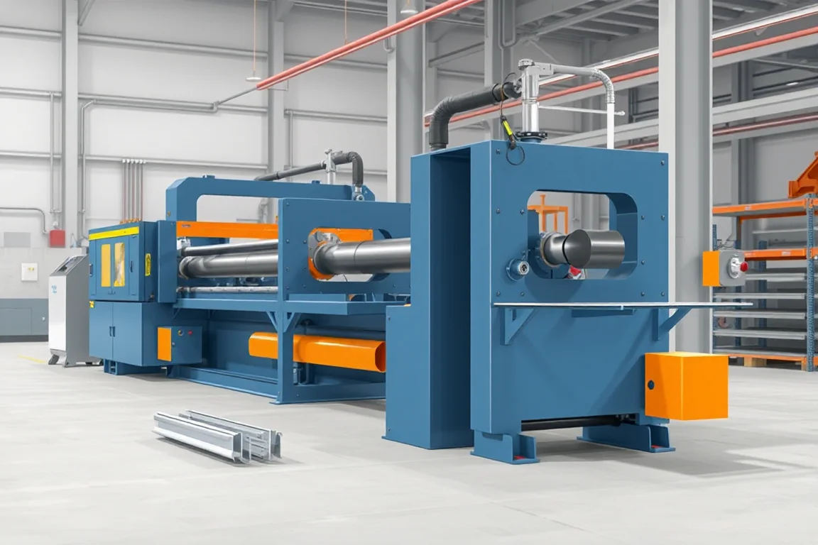
Storage-rack roll forming equipment produces several different members of a rack or shelving system. Uprights, beams and shelf panels have distinct section shapes, connections and finishing routes. A complete rack line may also need joining and assembly operations beyond the roll former. Define the finished components and their mating interfaces before comparing equipment packages.
Separate upright, beam and shelf production
Uprights typically need a repeated connection pattern tied to the section datums. Beams may require a defined closed-section or joined construction plus end connectors. Shelf panels have their own bearing edges, returns and possible reinforcement. Their shared use in storage does not make the production routes interchangeable.
- Rack Upright: review connector holes, section geometry and repeated pattern accuracy.
- Pallet Rack Beam: define beam construction, joining and end interfaces.
- Shelf Panel: identify seating, reinforcement and finished edge requirements.
- Storage Rack Line: map the operations needed for the complete component set.
Make the connection system the reference
Provide controlled drawings and actual mating connectors where practical. Commercial terms such as a particular hole style can describe a family without guaranteeing interchangeability. The hole shape, repeat, material and finished section must work with the chosen connector.
For beams and shelves, show what the supported component rests on and how the member attaches. An outside dimension alone may not define a seating step, joining clearance or end-connector relationship.
Include fabrication after forming
Ask what physically leaves each proposed line. An open beam section, a joined beam body and a completed beam with end connectors are different outputs. List the joining, fixtures, feature-making and inspection required between those stages.
Identify the finishing route as well. Inspect functional dimensions at the stage relevant to the supplied component. A satisfactory unfinished sample does not automatically establish the fit of a completed part after all required fabrication and coating.
Review size changes and material combinations
List each section with its grade, thickness and hole or end-feature schedule. Determine which adjustments and tool changes are needed between products. A nominal range of upright widths should not be treated as coverage of every connector pattern.
Measure changeover through the first accepted component and connection check. Include punch tools, cutting supports, joining fixtures and identification where relevant. Keep drawing and setup references together so similar members are not mixed.
Inspect the complete rack interface
Trial the intended beam connector with its upright and check representative repeated features over a useful length. For beams, inspect after the specified joining operations. For shelves, verify seating with the actual supporting members rather than checking a loose panel in isolation.
Rack capacity is a property of the defined system and its engineering, not a consequence of the former's ability to produce a section. Keep structural approval distinct from manufacturing acceptance and avoid uncontrolled local changes to make trial parts fit.
Compare completed-member delivery
Count acceptable uprights, completed beams or finished shelf panels over the intended order mix. Punching, joining, connector installation and packing can be the route's limiting stages. A strip-speed comparison alone can conceal those obligations.
Prepare the component and assembly drawings, material matrix, feature programs, finishing requirements and normal orders. The pages below clarify each route so quotations can cover the equipment actually needed to supply the chosen rack system.
Continue your research
- Rack Upright Roll Forming Machine
- Pallet Rack Beam Roll Forming Machine
- Shelf Panel Roll Forming Machine
- Storage Rack Roll Forming Line
- Teardrop Rack Upright Roll Forming Machine
- Pallet Rack Box Beam Roll Forming Machine
- Pallet Rack Step Beam Roll Forming Machine
- Slotted Angle Roll Forming Machine
- Mezzanine Floor Beam Roll Forming Machine
- How Storage rack roll forming machine Works
- How To Choose a Storage rack roll forming machine
- Storage rack roll forming machine Price: What Affects the Cost?
- Materials and Thickness for Storage rack roll forming machine
- Production Speed and Output of Storage rack roll forming machine
- Roller, Tooling and Forming Design for Storage rack roll forming machine
- Common Defects and Troubleshooting for Storage rack roll forming machine