
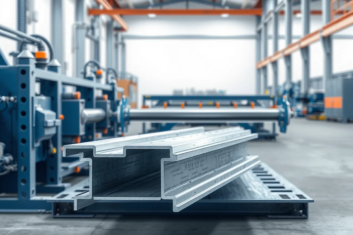
A storage rack roll forming line is a coordinated manufacturing project for the profiles and assemblies used in a specified rack catalogue. Uprights, beams, shelf panels and bracing do not share one universal production route. Each has its own section, feature pattern, joining requirements and role in the completed system.
The most useful starting document is therefore a component-to-process map. It shows which parts are roll formed, which need other fabrication, which are purchased and how they become complete accepted rack orders. This makes line balance and equipment boundaries clearer than a broad promise to manufacture all racks.
Which storage system will the factory supply?
Define the product family, such as a specified pallet-rack or shelving arrangement, and identify its components. Different systems can share similar-looking channels while using incompatible connectors or support details. The equipment plan should follow controlled drawings rather than generic catalogue categories.
Also decide the delivery boundary: loose profiles, fabricated beams and frames, or complete kits. That decision determines the joining, finishing, inspection and packing work needed beyond the roll formers.
How should components be mapped to production routes?
- Uprights: repeated connection features and a controlled open section.
- Beams: longitudinal profiles, any closed or paired construction and end connectors.
- Shelf panels: longitudinal edges, end details and optional reinforcement.
- Bracing: its specified section, length and connection preparation.
- Accessories: bases, connectors, locks and other parts made separately or purchased.
- Final stages: joining, finishing, inspection and order packing.
For each route, state the actual input and finished output. This prevents an intermediate formed blank from being counted as a complete rack component.
What should the product and material matrix contain?
List controlled drawing references, grade, thickness, strip width, length range and feature patterns for every family. Keep approved combinations together rather than combining unrelated maximum values into an assumed machine envelope.
Include expected quantities and change frequency. A line optimized for one large repeat order may not suit a business supplying many small configurations. The matrix should help compare tooling flexibility, coil preparation, inspection and stock requirements.
Identify future products separately. A new upright connector pattern or beam construction can require more than a software update, even if its commercial name resembles an existing item.
How should upright production be specified?
The upright route needs coordinated perforation and forming. Beam-connector openings, bracing features and end references must remain correct on the completed section. Trial the actual pattern and material, not only a plain profile.
Use intended beam connectors and frame components for fit checks. Measure section and opening geometry as well as assembly behavior. A connector forced into one selected opening is not a repeatable production result.
If complete frames are supplied, include bracing and base attachment with the required fixtures and inspections. The upright former alone does not deliver a finished frame.
How should beam production be specified?
Identify the exact construction: a step profile, a closed section or a member assembled from multiple formed elements. Include the seam or joining process and end-connector attachment. These can govern the production route as much as the main forming pass.
Inspect complete beams after all included joining. Check section, length, straightness and connector positions, then verify fit with the intended uprights. Keep the relevant connection and rack-performance qualification separate from the machine's dimensional acceptance.
Balance mating-part and connector supply. Producing excess beam bodies does not complete orders if required end parts or joining capacity are missing.
Where do shelves and bracing fit?
Shelf panels may need end forming, notching, reinforcement and surface protection beyond their longitudinal roll-formed edges. Bracing members have their own end and attachment references. Treat these as defined routes rather than miscellaneous work left to the factory after installation.
Where shared equipment is proposed, review the actual changes between products. A former capable of making several accessory shapes still needs appropriate tools, cutting components and inspection references. Include first-good-product recovery in the scheduling study.
Purchased shelves or braces can be a practical boundary for some projects. The important requirement is that the bill of materials and quality responsibilities make that choice explicit.
How should joining and finishing be coordinated?
Define the approved joining method for each assembly and the fixtures that establish its functional dimensions. A correct formed component can become an incorrect finished part if joining changes alignment or connector position.
Specify the finishing route and final inspection condition. Connector openings, seating surfaces and visible faces may need checks after coating and handling. An intermediate raw-part inspection should not be treated as final acceptance where later operations can change the product.
Keep material and component identity through subcontracted work. Similar colors and external dimensions do not make different grades, thicknesses or connector families interchangeable.
How can factory line balance be evaluated?
Convert the sales forecast into component demand and processing time at each route. Include forming, punching, joining, finishing, inspection and packing. The stage that limits complete orders may not be the most visually impressive machine.
For planning only, an order containing 100 frames and 300 beams needs the specified frame uprights, bracing, bases, beam bodies and connectors in matching quantities. The actual bill of materials depends on the rack design. Extra output from one route does not compensate for a missing component elsewhere.
Test both a long repeat order and a mixed order. The first reveals sustained production constraints, while the second exposes changeover, material and identification demands. Both should influence the equipment decision.
What should shared-line flexibility prove?
Request a transition matrix listing rolls, punches, guides, cutoff parts, programs and fixtures. Separate simple length changes from new sections or connector patterns. A general automatic-size claim is not a sufficient production plan.
Demonstrate meaningful transitions and return to prior accepted setups. Include inspection, assembly fit and setup scrap in first-good-product time. This shows whether the factory can repeat configurations rather than merely reach them once during commissioning.
Provide storage and safe handling for tools and change parts. A compact machine footprint can be misleading if routine changes need space that the layout does not provide.
How should order identification and packing work?
Define product references that distinguish section, material, length, pattern and finish. Preserve them from component manufacture through fabrication and dispatch. Similar parts should not depend on visual recognition by one experienced operator.
For kits, agree how components are grouped and counted. A complete kit check is more informative than a total metre counter when customers need a particular mix of frames, beams and accessories. Keep replacements and rejected parts visible in the order record.
Protect connector hooks, shelf edges and finished surfaces during movement. The acceptance trial should inspect normal packed output, not only components resting undamaged beside a machine.
What should the investment comparison include?
Separate common infrastructure, product-specific machines, tools, joining fixtures, finishing and inspection equipment. Add coil loading, lifting, utilities, training and commissioning. State which components remain purchased and which services are subcontracted.
Compare proposals against the same component catalogue and delivery boundary. A package making loose profiles is not equivalent to a factory producing finished rack kits. Clear boundaries make cost and expansion decisions more practical.
What should complete-project acceptance demonstrate?
- Representative components from every included route.
- Material identity and conformity to controlled drawings.
- Section, feature, length and end measurements.
- Required joining and final finishing checks.
- Fit of intended uprights, beams, shelves and accessories.
- Required production changes and recovered configurations.
- A complete identified order or kit after normal packing.
Retain reference components, mating hardware and setup records together. Manufacturing acceptance establishes the repeatable production baseline; complete rack design and load verification remain separately assigned responsibilities.
Frequently asked questions
Can one machine make an entire rack system?
Not automatically. Uprights, beams, shelves and accessories can require different forming, punching and joining routes. Use a component-to-process map to identify the actual equipment and purchased parts needed.
Which machine determines factory capacity?
It depends on the order mix. Punching, beam joining, frame assembly, finishing or packing may constrain deliveries. Measure complete accepted orders rather than the fastest isolated former.
Are different rack connectors interchangeable?
Do not assume so. Their openings, hooks and seating surfaces can differ. Use the controlled component family and intended mating parts throughout tooling review and acceptance.
Should coating be included in the equipment project?
Its route and responsibilities should be defined, whether in-house or subcontracted. Final fit, identification and inspection must account for it. Leaving finishing unspecified creates an incomplete delivery plan.
Does a successful sample rack establish a load rating?
No. Assembly fit is a manufacturing check. The complete rack requires its applicable engineering and qualification evidence. Do not convert a machine trial into a universal capacity claim.
What should be prepared first?
Create the component catalogue, drawings, material matrix and realistic order mix. Define whether the factory delivers profiles, fabricated components or complete kits. That information provides the basis for selecting and balancing the production routes.

Continue your research
- Storage Rack & Shelving Roll Forming Machines
- Rack Upright Roll Forming Machine
- Pallet Rack Beam Roll Forming Machine
- Teardrop Rack Upright Roll Forming Machine
- Pallet Rack Box Beam Roll Forming Machine
- Pallet Rack Step Beam Roll Forming Machine
- How Storage rack roll forming machine Works
- How To Choose a Storage rack roll forming machine
- Storage rack roll forming machine Price: What Affects the Cost?
Configuration & specification inputs
Match the configuration to your section drawing, material and production requirements.
| Parameter | Requirement / confirmation needed |
|---|---|
| Profile geometry | Controlled rack-component catalogue with distinct upright, beam, shelf and accessory interfaces |
| Material | Component-specific specifications preserved through fabrication and finishing |
| Thickness & grade | Approved material combinations defined separately for each production route |
| Process route | Coordinated component forming/features, joining, finishing, inspection and order packing |
| Cutting | Component-specific lengths and end details linked to the rack bill of materials |
| Output | Complete accepted rack orders or kits for the stated product mix |
| Electrical supply | Develop site utilities from all included routes and shared infrastructure |
| Acceptance | Verify representative components and mating assemblies, demonstrate changes and deliver an identified complete order |