
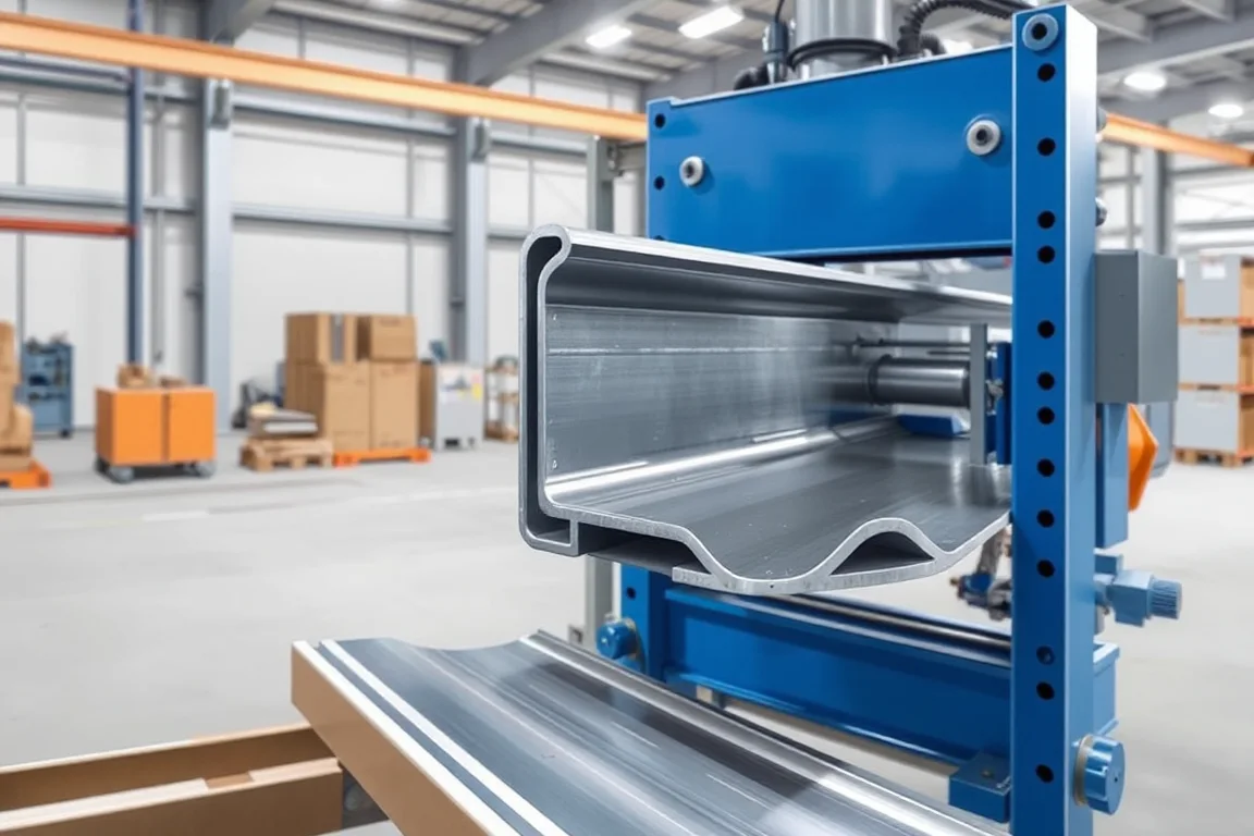
A slotted angle roll forming machine produces L-shaped sections that carry a repeated hole or slot pattern along one or both legs. The profile is commonly used in adjustable shelving, light storage racks and support frames where bolts, cleats or shelf brackets engage the holes. The machine is therefore not only a roll former. It is a coordinated punching, forming, cutoff and handling system, and the relationship between the slot pattern and the formed section determines whether the finished angle assembles correctly.
This article treats the slotted angle roll forming machine as an application-specific production line. It separates component production from assembly, certification and in-service performance. It also distinguishes this topic from teardrop upright, box beam, step beam and mezzanine beam lines, which serve different connection systems and structural roles.
What defines a slotted angle component
A slotted angle is an L section with a regular pattern of holes or slots. The pattern may run along the centreline of a leg, near the corner, or offset toward an edge. In racking and shelving, the holes provide vertical adjustment for shelf levels or connection points for brackets and cross members. The angle may be used as an upright, a horizontal support, a shelf rail or a frame member.
The drawing controls several features that interact: leg lengths, corner radius, hole pitch, hole size and shape, distance from the corner to the hole centreline, slot orientation and end cut. A change in any one of these can affect how the part fits with its mating component. For that reason, the slotted angle roll forming machine should be specified around an agreed component drawing rather than around a nominal angle size alone.
Why the hole pattern matters as much as the section
Roll forming produces the L shape by progressive bending. Punching creates the holes before, between or after forming stages. The sequence affects hole position, hole distortion and the flatness of the leg around the hole. If punching occurs before forming, the bending operation can stretch or shift the hole pattern slightly. If punching occurs after forming, the tooling must reach into a formed section, which can be more complex.
Hole pitch and corner distance are cumulative dimensions. Small errors at each station can accumulate along the length of the part. When the angle is used with a bracket or shelf clip, cumulative drift can make some positions fit tightly and others loosely. The machine acceptance process should therefore check repeated holes along a representative length, not only a single hole near the leading end.
Material and thickness inputs for the machine builder
The buyer should specify the base-metal grade, thickness and post-forming finish. Structural steel with a known yield behaviour forms differently from a softer commercial quality strip. Thickness variation within a coil affects both the punch load and the bend angle. If the machine is expected to run more than one thickness or grade, the operating range needs to be confirmed by the supplier against the actual profile.
The finish sequence matters. Pre-painted or coated strip can be damaged by punching burrs, roll contact and cutoff. Post-forming finishing, such as painting or galvanizing, can change hole size and edge condition. The production route should state whether finishing happens before or after forming so that inspection criteria match the finished part.
Punching and forming sequence options
A common process route is punching, section forming, cutoff, and welding or assembly where required, followed by inspection. The punching station creates the hole pattern. The forming stations bend the strip into the L section. The cutoff separates the part. Secondary operations may add end features, welded brackets or additional holes.
An alternative route places some punching after forming, or uses a separate press for hole patterns that are difficult to produce in the line. This can simplify roll tooling but adds a second operation and creates a new handling and location step. The choice depends on hole complexity, production volume and whether the holes must be formed before the legs close the access for punch tools.
Cutoff and end quality
Cutoff requirements are profile-specific. The cutoff tool must support the L section without crushing the legs or distorting the hole pattern near the end. Cut length accuracy matters for assembly, especially when angles are used in pairs or in frames. The cut end should be checked for burrs, deformation and squareness.
A practical acceptance question is whether the cutoff interrupts a slot or hole. If the cut passes through a hole, the remaining partial hole can have a sharp edge or reduced bearing area. The drawing should define how that end is treated: whether the partial hole is acceptable, removed by trimming, or avoided by adjusting the cut length. This is one of the clearest differences between a well-defined component and a generic angle.
Assembly boundaries: forming versus finished rack component
The slotted angle roll forming machine produces the angle component. It does not, by itself, establish the load capacity of a finished rack or shelving structure. Assembly operations such as attaching brackets, welding cross members, joining uprights or installing shelf panels are separate steps with their own quality requirements. A built-up frame may combine several formed components, fasteners and panels.
For this reason, machine acceptance should verify the agreed component drawing and the interfaces that the component controls. Rack load capacity must be established for the finished racking design, considering the complete assembly, connection method and service conditions. The machine supplier can be responsible for the formed component and its dimensional consistency, while the rack designer remains responsible for structural performance.
Inspection priorities for slotted angle
Inspection should cover the features that affect assembly. Check slot clearance by test-fitting the intended bolt, clip or bracket. Inspect edge condition for burrs or cracks. Measure section straightness and leg squareness. Review whether the cutoff has interrupted a slot and how that end has been treated. Verify hole pitch and corner distance at several positions along the part.
For product families that share leg sizes but use different fitting systems, keep separate inspection patterns. A common leg dimension does not mean the hole pattern is interchangeable. The drawing and the inspection plan should identify each family by its connection geometry, not only by the outer profile.
Comparing production routes for slotted angle
A dedicated slotted angle roll forming machine with integrated punching is suited to a stable product family and moderate to high volume. It reduces handling between operations, but the tooling is specific to the hole pattern and section. A separate press and roll forming line can offer more flexibility for multiple hole patterns, at the cost of additional setup and work-in-progress.
A general-purpose roll forming line with secondary punching may be appropriate for low volume or frequent pattern changes. However, it can be slower and may require manual handling that affects hole position. A complete rack component line, including welding and assembly, is a different scope from a bare forming mill. Commercial comparisons should separate punch tooling, roll tooling, welding or assembly scope and automatic handling so that unlike offers are not evaluated as equivalent.
Output and changeover considerations
Production output depends on punch density, line speed, cut length, coil handling and the time needed to change over between profiles or hole patterns. A single accepted output figure should be defined per shift with the actual profile and material, after all included operations. The buyer should record changeover steps, setup scrap, punching time and unloading time.
Power requirements should be confirmed from the equipment schedule. The buyer should state voltage, frequency and phase, and the supplier should provide a confirmed installed power schedule. The operating range for thickness and material requires supplier verification against the intended profile.
Practical checklist before approving a line
- Define the component drawing with leg lengths, hole pattern, slot orientation, end cut and any welded features.
- State material grade, thickness and finish sequence for each component.
- Confirm the process route from punching through inspection, including any secondary operations.
- Run the agreed material and profile in acceptance trials, not an easier demonstration substitute.
- Inspect first-off pieces and a representative steady-production sample with the agreed gauges.
- Record changeover steps, setup scrap, punching and unloading time.
- Test beam connector engagement with the upright where the angle is part of a beam connection.
- Review whether cutoff interrupts a slot and how the end is treated.
- Compare the written equipment scope with all secondary operations needed for a finished part.
- Separate component acceptance from rack load capacity and finished assembly certification.
Frequently asked questions
What is the difference between a slotted angle roll forming machine and a teardrop upright line?
A slotted angle machine produces an L section with a repeated hole or slot pattern, often for shelving and lighter frames. A teardrop upright line produces a different upright profile and hole shape associated with a specific rack connection system. The tooling, hole geometry and inspection criteria differ. They should not be treated as interchangeable without a drawing review.
Can one machine produce several hole patterns?
It can if the punching station is designed for changeable tooling and the control system stores the pattern. However, each pattern needs its own setup and first-off approval. If patterns share leg sizes but differ in hole pitch or slot shape, the machine may need separate punch tools or a different punching approach. The buyer should define how many patterns are required and how often they change.
Why does cutoff sometimes damage the slot pattern?
Cutoff applies force close to the end of the part. If the cutoff tool does not support the legs or if the cut passes through a hole, the edge can deform or leave a partial opening. The drawing should state whether partial holes are allowed. A profile-supported cutoff and a controlled cut length help maintain end quality, but the exact behaviour depends on the section and tooling.
How should I evaluate the production target?
Define accepted output per shift with the actual profile and material. Include punching, forming, cutoff and any handling or assembly operations that are part of the line scope. Measure the parts that meet the drawing after all included operations, not the speed of an empty forming mill. Changeover time and setup scrap should be counted separately.
What should I inspect on the first-off part?
Inspect the hole pattern at several positions along the length, leg squareness, section straightness, cut length and end condition. Test fit the intended bolt, clip or bracket. Check whether the cutoff has interrupted a slot and whether the end treatment is acceptable. Record the results against the agreed drawing before steady production begins.
Does the forming machine determine the rack load capacity?
No. The forming machine controls the dimensional quality of the angle component. Rack load capacity depends on the finished assembly, connection method, material properties, bracing and service conditions. Component acceptance and rack certification are separate activities. The machine acceptance process should focus on the component drawing and its interfaces.
Scope notes for quotation and approval
When comparing offers for a slotted angle roll forming machine, compare like scopes. A bare forming mill is not the same as a complete production line that includes punching, cutoff, welding or assembly and automatic handling. The quotation should identify which operations are included, which are excluded, and how the finished component will be inspected. This makes the commercial comparison meaningful and reduces the risk of an incomplete line arriving on site.

Continue your research
- Storage Rack & Shelving Roll Forming Machines
- Rack Upright Roll Forming Machine
- Pallet Rack Beam Roll Forming Machine
- Teardrop Rack Upright Roll Forming Machine
- Pallet Rack Box Beam Roll Forming Machine
- Pallet Rack Step Beam Roll Forming Machine
- How Storage rack roll forming machine Works
- How To Choose a Storage rack roll forming machine
- Storage rack roll forming machine Price: What Affects the Cost?
Configuration & specification inputs
Match the configuration to your section drawing, material and production requirements.
| Parameter | Requirement / confirmation needed |
|---|---|
| Profile geometry | Slotted angle requires a repeated hole pattern on an L section. Check how hole pitch, corner distance and burr direction are maintained through forming and cutoff. |
| Material | Specified structural steel with an agreed post-forming finish |
| Thickness & grade | Buyer to specify base-metal thickness and grade; operating range requires supplier verification. |
| Process route | Punching → section forming → cutoff → welding/assembly where required → inspection |
| Cutting | Confirm profile-supported cutoff, cut lengths, end quality and any secondary operations. |
| Output | Define accepted output per shift with the actual profile and material. |
| Electrical supply | Buyer to state voltage / frequency / phase. Installed power requires a confirmed equipment schedule. |
| Acceptance | Check slot clearance, edge condition and the assembled angle connection. Review whether cutoff interrupts a slot and how that end is treated. Keep separate patterns for product families that share leg sizes but use different fitting systems. |