
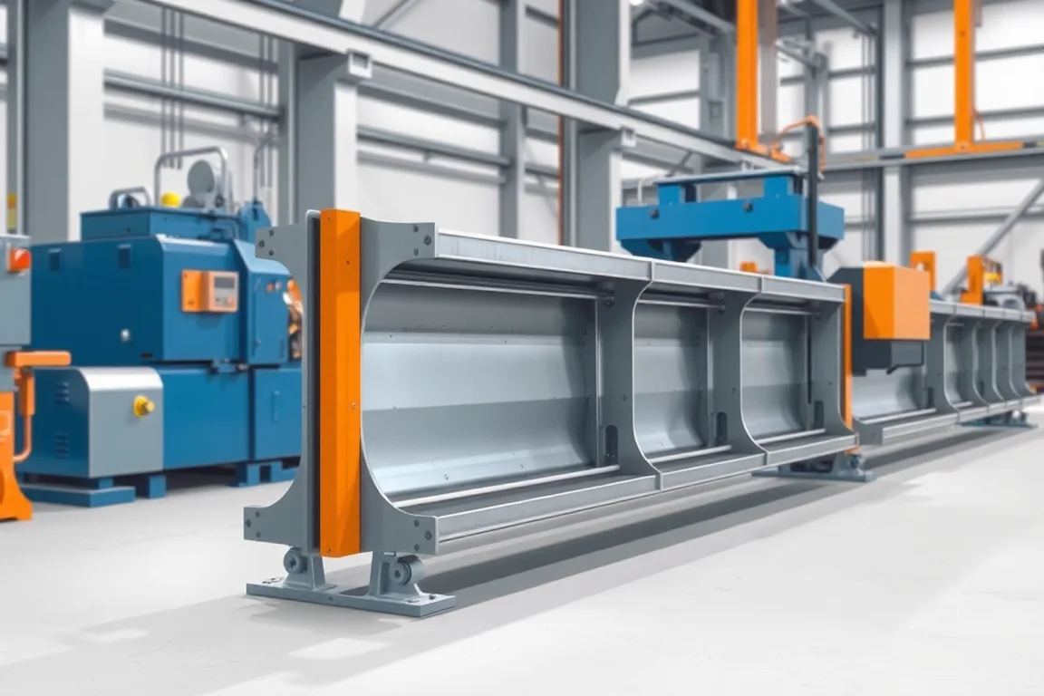
A guardrail sigma post roll forming machine produces a post with the specified folded sigma-like cross-section for a defined barrier system. The additional folds distinguish it from a simple C or U post and create particular connection and orientation requirements. The exact drawing, not the Greek-letter resemblance, must guide the tooling.
Sigma posts should be treated as controlled safety-system components. Their material, section, hole positions, length and coating route belong to the approved barrier specification. A machine trial establishes manufacturing accuracy, not the crash performance of a barrier assembled from arbitrary parts.
Which sigma geometry must be documented?
Show every web segment, flange, return, bend angle and radius. Define the overall width and depth alongside the internal dimensions that establish the folded shape. Mark the installed orientation and the surfaces used for connection features.
Provide a section drawing detailed enough to distinguish the intended sigma profile from another locally named variant. Similar outside dimensions can conceal different fold positions or contact surfaces.
How do the folds affect the forming proposal?
The rolls must develop the multiple bends progressively while preserving access and the intended relationships between faces. The material and fold geometry determine the sequence. A sigma post is not simply a U post with an extra bend added at the end.
Ask the supplier to review the complete section and material combinations. Include the final shape near cut ends in acceptance because local deformation can alter the connection surface even when the interior profile looks correct.
What should the barrier connection package contain?
Supply the approved spacer, bracket or rail interface and its fastener references. Show the post orientation in the assembly. Hole positions should be defined from clear finished-part datums and the designated end.
- Feature sizes and slot orientation.
- Longitudinal and transverse position references.
- Required solid zones and end shape.
- Component revision and identity.
- Representative mating parts for the trial.
Do not approve the post using a modified spacer or relocated connection. The purpose is to reproduce the controlled interface, not to find a way to make unrelated parts fit.
How should punching and cutting be arranged?
The proposal should explain where features are made relative to the progressive folds. Access to a surface can change as the sigma section develops. Final feature registration and edge condition should be demonstrated with the real product.
The cutoff must support the folded profile without unacceptable local crushing or flare. Inspect holes and section geometry near both ends, then compare with an interior measurement. This separates local process effects from general forming accuracy.
What material and coating information is required?
State grade, base-metal thickness and the specified corrosion-protection route. Identify whether coating is present before forming or applied after fabrication. These routes have different equipment and handling interfaces and should not be left ambiguous.
Keep material identity through forming and any downstream process. If post-fabrication coating is included elsewhere, agree the condition of parts delivered to that stage and the final inspection responsibilities. Coating should not be expected to hide a geometry deviation.
Can several sigma sizes share one line?
Only within a defined tooling matrix. Changes to internal fold spacing, flanges or returns can require different rolls and cutting support, even when overall depth changes little. List every required variant separately.
Demonstrate the change through a complete featured post and mating-interface check. Include guides, punches, cutoff parts, material setup and inspection in the transition. A partial stand movement does not show first-good-post recovery.
How should straightness and orientation be controlled?
Measure the delivered post on agreed supports without forcing the folded section into shape. Check straightness, twist and the relative position of connection faces. The section's asymmetry makes clear orientation references especially useful.
Use markings or bundle identification consistent with the component drawing. Similar sigma variants should remain distinguishable after normal handling and coating processes. Traceability helps prevent an otherwise accurate part from entering the wrong barrier assembly.
What should the manufacturing trial record?
- The controlled sigma-post drawing and material.
- All fold dimensions and angles.
- Hole registration and end condition.
- Connection fit with intended components.
- Straightness, twist and orientation.
- Coating-process handoff and part identity.
- Accepted output and required variant-change work.
Keep these manufacturing records separate from the complete barrier's performance assessment. They support repeatable component production but do not establish a new safety-system rating.
Frequently asked questions
Are all sigma posts interchangeable?
No. Fold geometry, material, holes and the barrier connection can differ. Use the exact controlled component drawing and approved system references.
Can C-post equipment form sigma without changes?
That requires a complete tooling review. The multiple folded faces, feature access and cutoff support differ from a basic C section.
Why is installed orientation important?
The folded faces and connection features have defined roles in the barrier assembly. Reversing or confusing the member can change how components meet even when overall dimensions match.
Does a forming trial cover galvanizing quality?
Only the explicitly included stages are covered. Define the coating route and final inspection responsibility separately from the roll-forming trial.
What should be provided for quotation?
Send the full folded section, material and coating specification, hole and end details, mating components and required variants. Identify the barrier-system revision that controls the product.
Control every fold and connection face
A sigma-post line should be evaluated through its full folded geometry and actual barrier interface. That produces a meaningful equipment specification and preserves the distinction between accurate manufacture and safety-system qualification.

Continue your research
- Guardrail & Crash Barrier Roll Forming Machines
- W Beam Guardrail Roll Forming Machine
- Thrie Beam Guardrail Roll Forming Machine
- Guardrail C Post Roll Forming Machine
- Guardrail U Post Roll Forming Machine
- Guardrail Spacer Block Roll Forming Machine
- How Guardrail roll forming machine Works
- How To Choose a Guardrail roll forming machine
- Guardrail roll forming machine Price: What Affects the Cost?
Configuration & specification inputs
Match the configuration to your section drawing, material and production requirements.
| Parameter | Requirement / confirmation needed |
|---|---|
| Profile geometry | Controlled sigma-post folded faces, flanges, returns, angles and barrier connection orientation. |
| Material | Approved component steel grade and specified pre- or post-fabrication coating route. |
| Thickness & grade | Grade-thickness combinations reviewed against the complete folded section. |
| Process route | Coil preparation, accessible feature sequence, progressive sigma forming, supported cutting and traceable handoff. |
| Cutting | Post lengths with preserved folded faces and correct hole-to-end relationships. |
| Output | Accepted complete sigma posts including required variant changes and identity checks. |
| Electrical supply | Utilities for the defined forming, punching, cutoff and discharge package. |
| Acceptance | Fold dimensions, connection faces, holes, orientation, straightness, twist and intended component fit. |