
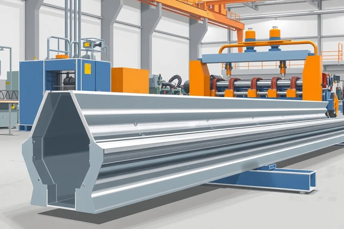
A W beam guardrail roll forming machine produces the corrugated rail elements specified for a particular roadside barrier system. The manufacturing target includes the beam cross-section, splice and attachment holes, finished length and coating route. A recognizable W-shaped outline is only the starting point.
The equipment project should follow the controlled barrier-component drawings. Rail, posts, spacers, bolts, terminals and transitions work within a defined system, so a machine trial must not be confused with verification of the complete barrier's crash performance. The useful production objective is accurate, traceable manufacture of the specified beam.
What defines the W beam product?
The profile contains two principal corrugations arranged according to its drawing, with terminal edges and bend geometry that establish the finished section. Rail length, hole pattern and splice relationship complete the component definition. Products described by the same broad name can still differ in material or attachment details.
Identify the intended barrier system and drawing revision before comparing tools. A supplier should not need to guess the required holes or substitute a locally familiar pattern. The manufacturing brief should be specific enough that accepted beams can be checked without reference to a marketing photograph.
Which drawings and material inputs are essential?
- Complete cross-section with corrugation geometry and measurement datums.
- Rail length, end shape and splice relationship.
- All holes or slots, including their orientation and position.
- Material grade, thickness and incoming condition.
- Required coating process and final inspection stage.
- Identification, bundling and traceability requirements.
Include mating rail and attachment references for trial assembly. If the approved system uses several rail lengths or special patterns, list them individually. An adjustable length control does not automatically create every corresponding hole pattern correctly.
How does the line produce a W beam?
The route combines coil handling, preparation, feature-making, progressive forming, length production and collection. The location of punching and cutting depends on the proposed equipment. The supplier should explain how finished holes and ends remain referenced to the required beam geometry.
- Identify and present the approved coil to the production route.
- Control strip entry and any required preparation.
- Produce the specified attachment and splice features.
- Develop the corrugations through the forming passes.
- Cut the released beam length with appropriate section support.
- Inspect and group the formed components for the next finishing or dispatch stage.
Ask how the process handles startup material, punched scrap and rejected beams. These flows need defined space and identification so they do not interfere with accepted production or become mixed into a bundle.
Why are hole patterns central to acceptance?
The splice and attachment pattern determines whether the beam connects with its intended components. Specify feature size, orientation and position from the finished datums. A hole in the correct general region is not enough if its relationship to the rail end or corrugation is wrong.
Check the complete beam after forming and cutting. Features created on flat strip may occupy a different spatial relationship after the section develops, so final inspection must address the delivered component. Inspect burr condition and local distortion as separate observations.
Assemble representative overlapping rails using the specified components and sequence. Record alignment and any need for unplanned forcing. Do not enlarge or alter holes during the demonstration merely to make an otherwise incompatible set appear acceptable.
How should grade and thickness be reviewed?
List the actual material combinations required by the component design. Strength, thickness, width and forming response belong together. The machine and tooling review should use that envelope rather than a single convenient thickness value.
Retain material identity through production and the selected finishing process. If a finished beam deviates in geometry, the team should be able to connect it to the coil, setup and inspection record. This is particularly important when several material specifications produce similar-looking rails.
Use the intended material in trials and document any substitution. A successful run on another grade can be useful development information, but it is not the same as demonstrating the specified commercial product.
Where does coating fit into the manufacturing route?
Define whether the project uses a specified coated input or a finishing operation after fabrication. Follow the approved component requirements rather than assuming the routes are interchangeable. The equipment scope should state what surface preparation or downstream handling remains outside the former.
Where finishing occurs later, identify which dimensional and surface checks are performed before and after that stage. Record any changes introduced during handling or processing. A formed beam that passes an intermediate check still needs the required final acceptance before delivery.
Include storage and transport between operations in the layout. The condition and identification of the rail must survive that movement without losing the connection to its production batch.
Can the same equipment make W beam and thrie beam?
A suitably configured system may cover both, but the required tooling and process changes must be explicit. The profiles differ in their corrugated section, and their material, feature and handling requirements need individual review. A product-name list is not a changeover plan.
Request a matrix of rolls, guides, punch tools, cutting components and settings for each beam. Demonstrate a representative transition through to a measured accepted part. Include tool handling, startup scrap and inspection in the first-good-product time.
If only W beam is needed, compare a dedicated arrangement against the broader package using the actual production forecast. Unused flexibility can add complexity, while insufficient flexibility can make future approved variants expensive to introduce.
What should straightness and end checks reveal?
Inspect production-length beams under a defined support condition. Measure the cross-section at agreed locations and compare the cut ends with the central portion. End distortion can affect splices even when the main corrugations are acceptable.
When a beam appears bowed or twisted, record whether the condition exists immediately after forming or appears later in handling or finishing. That sequence helps locate the source. Corrective work should follow the responsible engineering and equipment procedures rather than uncontrolled reshaping.
How should handling and bundling be planned?
Define nesting orientation, bundle quantity and the method used to move finished rails. The handling arrangement should protect holes, edges and the required finish while allowing reliable counting and identification. Long rail elements also need sufficient discharge and inspection space.
Separate different lengths, patterns and material specifications with clear labels. Similar corrugated profiles can be mistaken for one another once nested. Include a designated route for rejected parts and for material awaiting a later finishing or inspection stage.
What is a meaningful production-rate comparison?
Compare accepted beams of the specified length, material and hole pattern over a representative order. Punching, cutting, coil replacement, inspection and bundle removal can govern the complete cycle. A forming-speed figure with feature operations omitted does not represent finished rail output.
For planning arithmetic only, 250 accepted rails at a specified 4-metre component length contain 1,000 metres of manufactured rail. Installed barrier length is a different calculation because the system's overlaps and special components must be considered. Keep those quantities separate.
Compare quotations for equivalent tooling, coil handling, feature equipment, cutting, takeoff and inspection scope. Identify coating, component qualification and system approval responsibilities separately from the forming-line supply.
What should the acceptance trial prove?
- Section geometry in the agreed material.
- Finished length, end condition and feature positions.
- Splice compatibility using production-intent components.
- Straightness and twist under the defined measurement method.
- Required pattern or profile changes and recovered production.
- Bundle identification and handling condition.
- Accepted output and a record of all deviations.
Preserve the drawings, material records and reference samples from the trial. They establish the manufacturing baseline without implying that the machine itself certifies the complete roadside installation.
Frequently asked questions
Does making the W shape establish barrier compliance?
No. The rail is one component in a defined system. Material, holes, posts, attachments, terminals and installation all matter to the approved arrangement. Machine acceptance verifies the specified manufacturing output, not crash performance by itself.
Can hole patterns be changed through the controller?
Only within the capabilities of the installed feature tools and controls. Different shapes, positions or combinations may need other tooling. Supply every required pattern and demonstrate the relevant changes.
Is galvanizing part of the roll forming machine?
Not automatically. The coating route must be specified separately and coordinated with fabrication and inspection. Confirm the supply boundary so a former is not mistaken for a complete finishing plant.
Can the line also make posts?
Posts are separate profiles with their own material and feature requirements. They need an explicit production review and tooling scope. A beam line does not automatically manufacture all barrier components.
Why assemble overlapping rails during a trial?
It checks the combined effect of end geometry, corrugations and hole positions. Individual measurements remain necessary, but the controlled splice trial exposes incompatible assumptions that separate checks can miss.
What should an enquiry include?
Provide the controlled rail drawing, material, hole patterns, lengths, finishing route and expected quantities. Add traceability and bundling requirements. This gives the proposed line a precise W-beam manufacturing target.

Continue your research
- Guardrail & Crash Barrier Roll Forming Machines
- Thrie Beam Guardrail Roll Forming Machine
- Guardrail Post Roll Forming Machine
- Guardrail C Post Roll Forming Machine
- Guardrail Sigma Post Roll Forming Machine
- Guardrail U Post Roll Forming Machine
- How Guardrail roll forming machine Works
- How To Choose a Guardrail roll forming machine
- Guardrail roll forming machine Price: What Affects the Cost?
Configuration & specification inputs
Match the configuration to your section drawing, material and production requirements.
| Parameter | Requirement / confirmation needed |
|---|---|
| Profile geometry | Controlled W-beam corrugations, terminal edges and splice geometry |
| Material | Approved rail grade and thickness linked through fabrication and finishing |
| Thickness & grade | Trial the required grade, thickness and strip-width combinations |
| Process route | Identified coil, required preparation and holes, corrugation forming, cutoff and collection |
| Cutting | Check rail-end shape and splice condition after normal discharge |
| Output | Accepted patterned rails for the stated material and order, including inspection |
| Electrical supply | Confirm utilities for rail forming, punching, cutoff and bundle handling |
| Acceptance | Measure section and finished holes, assemble intended splices and retain material/setup records |