
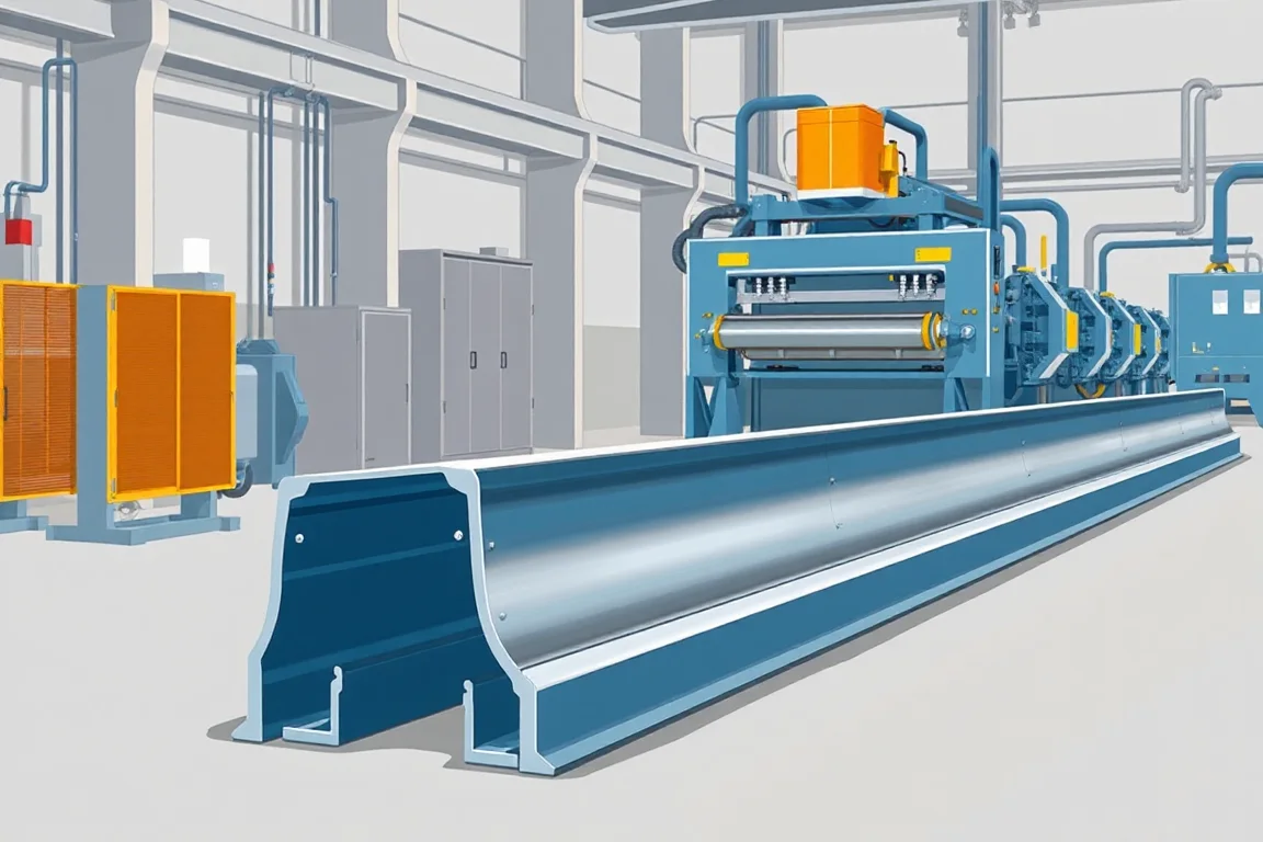
A thrie beam guardrail roll forming machine produces the three-corrugation rail components specified for a particular safety-barrier system. The additional corrugated geometry changes the forming and handling task compared with a W beam, while the splice pattern, attachment features and finishing requirements remain equally important parts of the product definition.
The right starting point is the controlled thrie-beam drawing and its intended component interfaces. The machine should be evaluated for manufacturing that rail accurately and repeatably, not for a general promise that a larger-looking beam automatically provides a particular roadside performance.
How does thrie-beam geometry affect production?
The profile contains three principal corrugations arranged to the approved section. Their relative position, depth, terminal edges and bend geometry establish the forming target. The wider developed strip and the completed cross-section need suitable guidance, roll development, cutoff support and collection.
Do not reduce the specification to a comparison with W beam. Thrie-beam products can have their own material, lengths and feature patterns, and the equipment enquiry should state those directly. A drawing labeled three-wave is still incomplete if it omits the functional holes and end relationships.
What should the component package show?
- Full cross-section with all corrugations and terminal edges.
- Material grade, thickness, input width and surface condition.
- Finished lengths and splice overlap references.
- Attachment and splice holes or slots with clear datums.
- Required coating route and final inspection requirements.
- Mating rail, spacer or attachment components used for fit checks.
Identify special rail variants separately. Transition pieces, terminal-related parts or locally modified sections may require other processes and should not be assumed to emerge from the same straight-profile route.
How should the forming sequence be reviewed?
The supplier should explain how the strip develops into the three-corrugation section without losing the specified relationship between its center and edges. The sequence must be assessed with the actual material range, not merely by counting forming stations.
Ask how entry alignment is established and how the completed section is supported near feature and cutting operations. A small lateral shift can matter when holes and corrugations need a controlled relationship. The production trial should therefore inspect both geometry and feature position on the same finished parts.
Retain the approved setup references. When the line later changes material or returns from another profile, operators need a repeatable recovery method rather than an informal visual adjustment.
What is the complete production route?
- Receive and identify the specified coil.
- Load, guide and prepare the strip for the proposed process.
- Produce the required holes or slots in the agreed sequence.
- Develop the three-corrugation profile through successive passes.
- Cut the ordered rail length with section-appropriate support.
- Inspect and group the component for its specified finishing or dispatch stage.
The position of punching and cutting can vary by equipment design. Require a clear explanation of the final datums and control method, including how feature positions remain correct when length or pattern changes.
Why should material combinations be tested individually?
Grade, thickness, width and coating condition jointly affect the production duty. A trial at one convenient combination does not establish results across a broad catalogue. Select representative combinations that reflect both normal orders and the demanding part of the required range.
Record coil identity with section measurements and feature observations. If a later batch differs, compare the material and setup before assuming that the tools have moved. This evidence supports a controlled investigation and avoids correcting the wrong cause.
Keep material and component identification through downstream finishing. Similar-looking rails from different specifications should not become indistinguishable merely because they share a coating color or nesting shape.
How should holes and splices be verified?
Measure features from the finished beam's controlled references. Check size, orientation, spacing and the relationship to each end. Inspect burrs and local deformation separately from positional accuracy.
Assemble a representative splice using normal production rails and the specified components. Confirm that the corrugations nest as intended and that the holes align without unplanned modification. Include more than one pair where the trial order permits, rather than selecting a single unusually convenient match.
If assembly is difficult, separate errors in section shape, end geometry and feature location. Changing a hole position to compensate for an incorrect section can conceal the source while moving the part away from its approved drawing.
What changes when W beam is included in the same project?
A combined production system must identify the tools and settings used by each profile. Review the feed path, forming tools, punches, cutoff components and discharge supports. The machine should not be described as universal merely because both profiles belong to the guardrail category.
Demonstrate thrie-to-W and return changeovers using the intended materials and patterns. Include inspection and startup scrap in the first-good-product time. A rapid movement of one tool assembly is only part of the complete production transition.
Compare the expected schedule with a dedicated arrangement. If thrie beam represents sustained demand, dedicated production may simplify scheduling; if it is intermittent, a configured shared route may be practical. The order mix should drive the decision.
How should coating and downstream work be scoped?
Follow the coating route required by the approved component specification. State whether the former processes a defined coated input or sends fabricated rails to a later finishing operation. Those routes have different material, handling and inspection implications.
Where finishing is separate, identify the checks required before and after it. Geometry, surface condition and product identity must remain controlled through transport and processing. Do not treat an intermediate forming inspection as final release of a finished component.
Special bending, end treatment or transition manufacture should have its own equipment scope. A straight thrie-beam former should not be assumed to make all shaped or system-specific accessory pieces.
What handling problems should be prevented?
The wider corrugated section needs a discharge and stacking arrangement matched to its geometry. Define nesting orientation, bundle quantity and lifting method. Provide room for inspection and for removing completed bundles without obstructing the next rail.
Inspect end and edge condition after normal collection. Handling can introduce local distortion that was absent at the last forming stand. A useful trial follows the rail through the actual route rather than judging it only before takeoff.
Labels should distinguish profile, pattern, length, material and production reference. Maintain separate areas for accepted rails, rejected parts and components awaiting another process.
How should useful output be compared?
Use accepted finished components for a stated order with the required holes and normal inspection active. Feature-making, cutting, coil changes and collection may set the complete-line rate. A run that omits the actual punch pattern does not show commercial thrie-beam output.
When reporting material length, distinguish component length from installed barrier coverage. Splices and special pieces belong to the system layout. A metre counter at the former cannot independently calculate the completed roadside installation.
Compare quotations with equivalent product matrices, tools, handling and acceptance scope. Coating, component testing and barrier-system qualification should be identified separately so neither the cost nor the responsibility is hidden inside a vague complete-line description.
What should acceptance demonstrate?
- Three-corrugation geometry and terminal-edge condition.
- Finished length and all feature positions.
- Splice fit with the intended mating components.
- Straightness and twist under agreed support conditions.
- Required changes of pattern, material or profile.
- Condition and identification of normal bundles.
- Accepted quantities, rejects and unresolved deviations.
Retain samples and setup records for each demonstrated configuration. Manufacturing conformity gives the production team a controlled baseline; it does not by itself establish crash performance for a complete barrier arrangement.
Frequently asked questions
Is thrie beam simply a wider W beam?
It has a different three-corrugation section and must follow its own drawing, material and feature requirements. Treat it as a distinct product configuration rather than assuming that widening a W-beam setup reproduces it.
Can one machine make both profiles?
A suitable combined system can, but its tooling and changeover arrangement must be specified and demonstrated. Include punches, cutoff and handling in the review, not only the main roll tools.
Does a larger rail automatically provide a higher barrier rating?
No. Performance belongs to the defined complete barrier system and its relevant evidence. Rail shape alone does not establish the result. Manufacture the approved component rather than inferring a rating from appearance.
Can the line produce transitions and terminals?
Only if the required shapes and operations are explicitly included. Such parts can need separate forming, bending or fabrication routes. List them individually in the project instead of assuming all accessories share the straight-beam process.
Why inspect after normal stacking?
Collection and bundle handling can change local edges or ends. The saleable component must remain acceptable after those operations. A trial that stops at the forming exit misses that part of the production route.
What should be supplied first?
Provide the controlled section, hole patterns, lengths, materials and coating route. Include mating-component references and expected orders. These inputs support a precise thrie-beam line and acceptance specification.

Continue your research
- Guardrail & Crash Barrier Roll Forming Machines
- W Beam Guardrail Roll Forming Machine
- Guardrail Post Roll Forming Machine
- Guardrail C Post Roll Forming Machine
- Guardrail Sigma Post Roll Forming Machine
- Guardrail U Post Roll Forming Machine
- How Guardrail roll forming machine Works
- How To Choose a Guardrail roll forming machine
- Guardrail roll forming machine Price: What Affects the Cost?
Configuration & specification inputs
Match the configuration to your section drawing, material and production requirements.
| Parameter | Requirement / confirmation needed |
|---|---|
| Profile geometry | Three-corrugation rail section with controlled ends and attachment features |
| Material | Specified thrie-beam material with traceability through the coating route |
| Thickness & grade | Approve actual grade, thickness and width combinations |
| Process route | Coil preparation, required feature-making, three-corrugation forming, supported cutoff and grouping |
| Cutting | Preserve the wider profile and end geometry required for splice assembly |
| Output | Accepted thrie rails with required hole patterns and normal handling included |
| Electrical supply | Confirm loads for the selected forming, punching, cutting and collection package |
| Acceptance | Measure section and hole datums, check splice fit and demonstrate required profile recovery |