
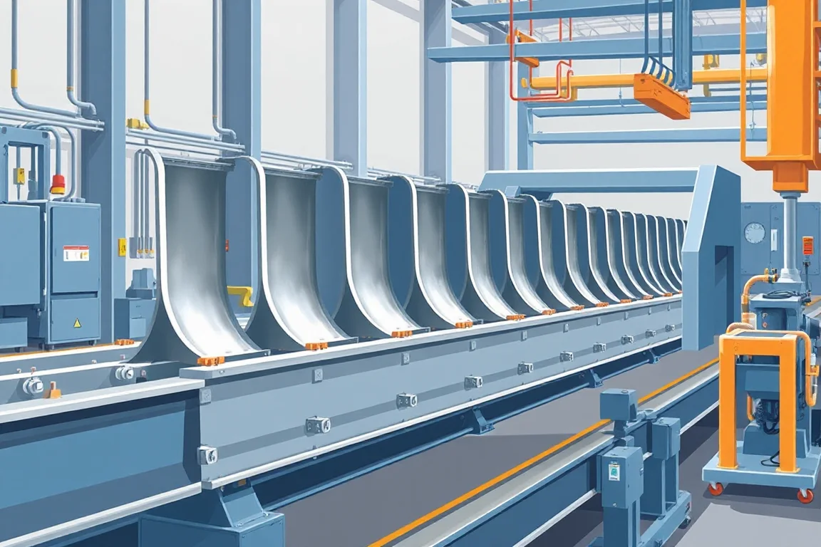
Production speed is the rate at which a roll forming line converts coil into accepted guardrail beam. It is not a single number stamped on the machine. It is the result of a sequence of operations, each with its own cycle time and reliability. Two lines with identical forming sections can deliver different output per shift because of differences in punching, cutoff, handling, inspection and downstream coating capacity.
Why "speed" is a system property, not a machine label
The line is a chain of dependent processes. The slowest stable step sets the pace. If punching cannot keep up with forming, the forming section runs intermittently. If the cutoff cycle is longer than the pitch between cut lengths, the line pauses between cuts. If a downstream coating or assembly step cannot absorb the finished beam, finished material accumulates and the line stops. A nominal running speed describes only one link in that chain.
For buying and planning, distinguish three quantities: steady running speed, actual running minutes, and good-output fraction. The first is the speed the line can hold while producing acceptable profile. The second is the portion of a shift when the line is actually running, after setup, coil changes, punch changes, minor stoppages and unloading pauses. The third is the share of material that passes inspection without rework or rejection. Accepted output is the product of these three, not the steady speed alone.
How the process sequence creates the output ceiling
A typical layout follows: leveling, punching, beam forming, cutoff, then coating or assembly operations as specified. Each step has interfaces that matter.
Leveling receives coil and presents flat, low-stress strip to the punch and forming sections. Poor leveling shows up later as twist, camber or inconsistent hole position. Punching creates bolt slots and other openings before or during forming, depending on the tooling concept. The punch cycle, number of hits per length, and any pattern change time directly affect line rhythm. Beam forming bends the strip into the wave profile. The number of forming stations and the way the profile is supported determine whether the line can run continuously without marking or distortion. Cutoff separates the formed beam at the specified length. The cutoff concept must match the profile and the end quality required. Coating or assembly operations, if in line, add their own cycle time and can become the pacing step.
The interface between punching and forming is especially important. If holes are punched before forming, the forming section must preserve hole position and shape. If punching occurs after forming, the tooling must reach the formed geometry and the line may need to stop for each punch set. The choice affects both speed and dimensional control.
Component production versus assembly, certification and in-service performance
Roll forming produces a component: the beam with its wave geometry and hole pattern. Assembly of the barrier system, certification of the system and in-service performance are separate activities. Production speed concerns component output. Dimensional acceptance of the beam is necessary but not sufficient for system approval. Keep these stages distinct when specifying output, so that line capacity is not confused with installed system performance.
Defining accepted output per shift with the actual profile and material
There is no verified model rating for this category. The meaningful metric is accepted output per shift for a defined profile, material and product mix. Define the following before comparing offers:
- The exact beam profile, including wave geometry, bolt-slot pattern, lap orientation and post connection geometry.
- The specified barrier-system steel, base-metal thickness and grade, with the operating range to be verified by the supplier.
- The coating sequence agreed between buyer and supplier, including whether coating is in line or offline.
- The intended cut-length and hole-pattern mix, because frequent changes reduce effective output.
- The inspection criteria for wave geometry, splice-hole position, lap fit and beam length.
Accepted output should count only material that passes these criteria. Rejected or reworked material is not output; it is a cost.
How to plan output without inventing machine ratings
Use a planning formula that separates the variables: accepted length equals steady running speed multiplied by actual running minutes multiplied by good-output fraction. The steady running speed is the speed the line holds while producing acceptable profile for the specific job. Actual running minutes are measured, not assumed from nominal shift length. The good-output fraction reflects the yield after inspection.
For product mix, divide by the representative cut length only when the mix and cutoff cycle permit that simplification. If lengths change often, treat each length as a separate planning case. Account explicitly for coil changes, setup, punch changes and unloading. These events consume minutes that are not available for forming.
Where output is usually lost: the real bottlenecks
Output loss rarely comes from the forming section alone. Common bottlenecks include:
- Punching: multiple hits per length or slow pattern changes can pace the line.
- Cutoff: a cutoff cycle longer than the time between cuts forces pauses.
- Coil changes: splice time and threading time reduce running minutes.
- Setup and changeover: profile or length changes that require tooling adjustment.
- Unloading and stacking: finished beams must be removed at a rate that matches production.
- Inspection: if inspection is manual and slow, it can back up the line.
- Downstream coating or assembly: if these operations cannot absorb the beam rate, the line stops.
Measure each step rather than assuming the forming section is the limit.
Comparing alternatives: tradeoffs that affect speed
When comparing line concepts, consider these tradeoffs:
- Punch before forming versus after forming: before forming can allow continuous punching and faster cycles, but hole position must survive forming. After forming may offer better hole quality but can require stopping for each punch set.
- In-line coating versus offline coating: in-line coating integrates the process but adds a step that can pace the line. Offline coating decouples the steps but adds handling and logistics.
- Flying cutoff versus stationary cutoff: a flying cutoff can cut on the move and reduce pauses, but it requires more complex synchronization and profile support. A stationary cutoff stops the line for each cut.
- Manual versus automated handling: automated unloading and stacking can reduce non-running time, but adds complexity and maintenance.
- Number of forming stations: more stations can improve profile quality and allow higher stable speed, but increase line length, cost and setup time.
There is no universal best choice. The right balance depends on the product mix, material, quality requirements and available floor space.
Practical checklist for assessing guardrail roll forming machine production speed
- Define the exact profile, material, thickness range and coating sequence.
- State the intended product mix and cut-length pattern.
- Measure actual running minutes over a representative shift, excluding setup and coil changes.
- Count accepted output separately from rejected or reworked material.
- Identify the pacing step by observing where the line waits.
- Confirm the cutoff concept matches profile and end quality requirements.
- Verify that downstream coating and assembly capacity can absorb the beam rate.
- Agree inspection criteria for wave geometry, splice-hole position, lap fit and beam length.
- Keep component dimensional acceptance separate from system crash-testing and installation approval.
- Document any assumptions about steady running speed and good-output fraction.
Acceptance and the difference between dimensional quality and system approval
Production speed is only useful if the output is accepted. Acceptance of the beam as a component involves checking wave geometry, splice-hole position, lap fit and beam length against the approved drawing. This dimensional acceptance is separate from system crash-testing and installation approval. A line that produces dimensionally acceptable beams may still feed a system that requires separate certification. Keep these boundaries clear when planning output and when evaluating supplier claims.
FAQ: specific questions about production speed and output
How do I calculate accepted output per shift without a machine rating?
Measure steady running speed for the actual profile and material, then measure actual running minutes in a shift. Multiply those by the good-output fraction, which is the share of material passing inspection. Count only accepted material. Do not use nominal shift minutes or unverified speed claims.
Which operation most often limits guardrail roll forming line output?
It varies by line and product. Punching and cutoff are common limits because their cycle times are discrete and can exceed the forming pace. Coil changes, setup and unloading also consume running minutes. Observe the line to see where it waits, rather than assuming the forming section is the bottleneck.
Does in-line coating increase or decrease production speed?
In-line coating adds a process step that can pace the line, so it can reduce output unless coating capacity matches forming. Offline coating decouples the steps but adds handling. The choice depends on the required coating sequence, quality and logistics.
How does product mix affect effective production speed?
Frequent changes in cut length or hole pattern require setup time and may force slower running. Each change reduces running minutes. Planning should treat different lengths as separate cases and account for changeover time explicitly.
What is the difference between running speed and accepted output?
Running speed is the speed the line holds while producing acceptable profile during a stable run. Accepted output is the total length that passes inspection over a shift, after accounting for stoppages, setup and rejects. The two are related but not interchangeable.
Can I compare production speed between two suppliers' machines?
Only if both are evaluated on the same profile, material, thickness, coating sequence and product mix. Ask for output defined as accepted length per shift under those conditions, and separate component acceptance from system approval. Without a common basis, speed claims are not comparable.
Why this matters for buying and planning
A guardrail roll forming machine is a production system. Its output is determined by the slowest stable step, the actual running minutes, and the yield of accepted material. Buying on a nominal speed figure alone can lead to a line that disappoints in real production. By defining the profile, material, product mix and acceptance criteria, and by measuring running minutes and good-output fraction, a buyer can compare alternatives on a realistic basis and plan capacity that matches downstream operations.
Continue your research
- Guardrail & Crash Barrier Roll Forming Machines
- W Beam Guardrail Roll Forming Machine
- Thrie Beam Guardrail Roll Forming Machine
- Guardrail C Post Roll Forming Machine
- Guardrail Sigma Post Roll Forming Machine
- Guardrail U Post Roll Forming Machine
- How Guardrail roll forming machine Works
- How To Choose a Guardrail roll forming machine
- Guardrail roll forming machine Price: What Affects the Cost?