
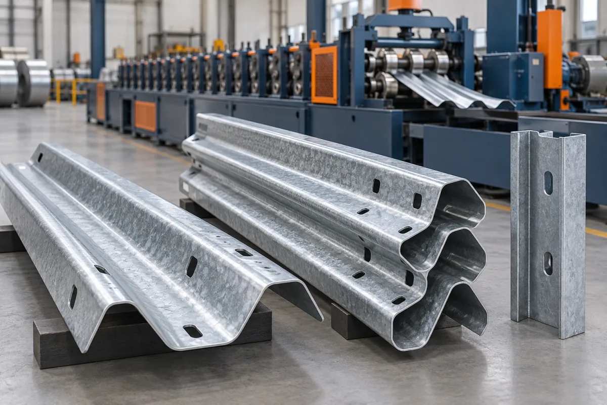
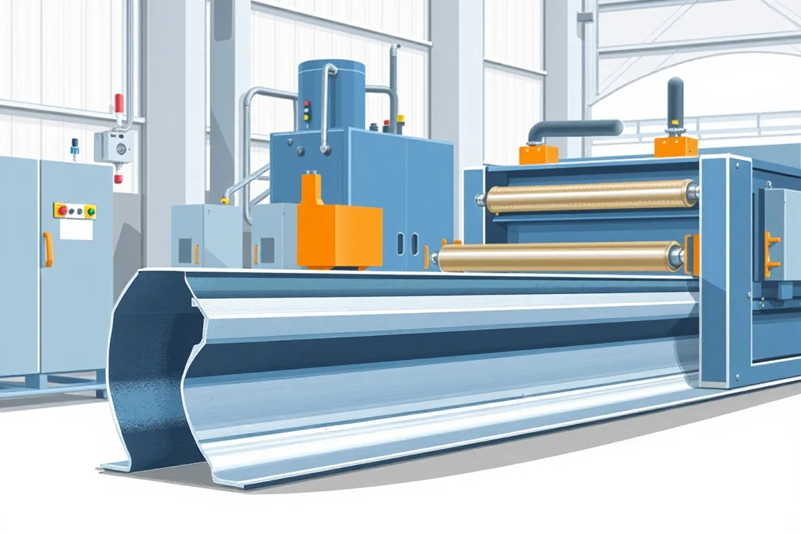
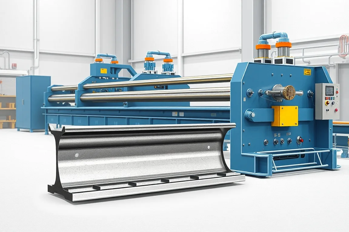
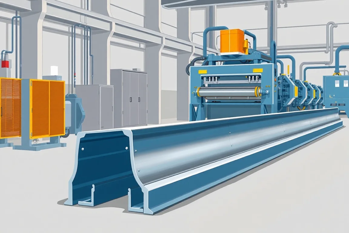
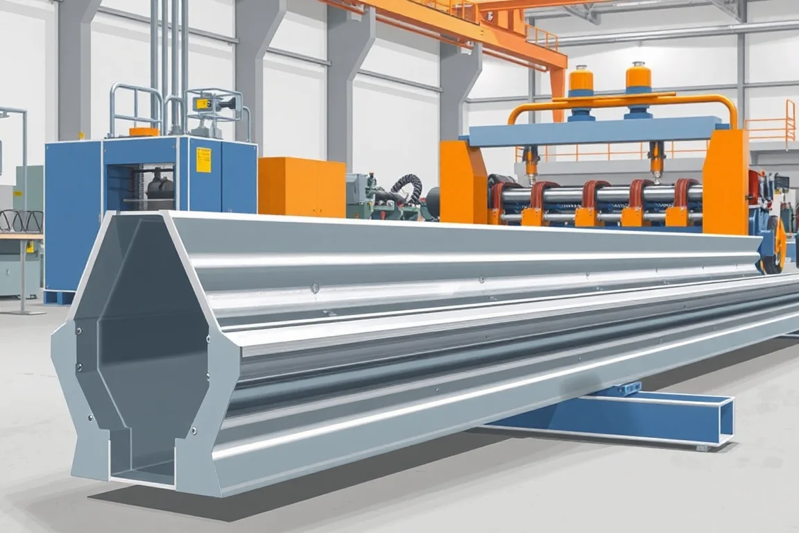
Guardrail roll forming equipment produces components for a defined road-barrier system. W-beam rails, thrie-beam rails, posts and spacers are different parts, with different geometry and process requirements. The starting point is the controlled component drawing and complete manufacturing route, not an assumption that one guardrail machine makes an entire roadside restraint system.
Identify the component before comparing lines
Rails need their specified profile, end relationship and connection features. Posts can use distinct open or shaped sections, while spacers may require short-part forming and additional fabrication. These differences affect punching, cutting, handling and any later coating.
- W Beam: review the two-wave rail profile and its connection references.
- Thrie Beam: define the different rail geometry and required system interfaces.
- Guardrail Post: select the actual post section and connection route.
- Crash Barrier Line: map which components and operations the package includes.
Use the barrier-system drawings as manufacturing targets
Specify material, section geometry, holes, slots, ends and the required finished condition. Similar-looking rails or posts should not be assumed interchangeable. A product's intended role in a barrier system makes accurate connection and component references particularly important.
Machine acceptance confirms manufacture to the agreed drawings. Qualification of the assembled barrier involves its complete design, components and installation. Do not interpret the ability to form a rail as evidence of crash performance or system approval.
Coordinate punching, forming and later processing
Show the proposed sequence for creating connection features and forming the section. Identify datums used before and after forming and how they relate to cut ends. A correctly shaped rail with incorrectly referenced holes is not a completed conforming part.
Specify whether the material is coated before processing or follows a defined later finishing route. Include any downstream fabrication and inspection. A quotation that stops at an unfinished formed length should make that boundary explicit.
Match the equipment to the material and handling duty
Pair grade, thickness, width and component geometry. Review actual combinations rather than combining unrelated maximum capacity figures. Include coil loading, strip preparation, cutoff and finished-part movement in the equipment plan.
Use the manufacturer's safe operating and service procedures for the installed equipment. Heavy or stored-energy handling tasks should not be reduced to improvised adjustments during a production trial. The acceptance plan should identify competent personnel and the defined operating route.
Inspect complete components and interfaces
Measure section geometry and connection features after all specified operations. Trial the intended rail lap, post or spacer interface where relevant. Record distortion, hole mismatch or coating-related issues rather than modifying parts locally to make a demonstration fit.
For long components, agree support and measurement conditions for straightness and twist. Compare results at appropriate process stages to locate the cause of a deviation. Keep tooling and drawing revisions traceable to the approved part.
Build a complete equipment and output comparison
Count accepted finished components, not simply formed metres. Hole programs, cutoff, handling and downstream work influence the delivered result. Compare quotations using the same component set and assign responsibility for any work outside the proposed line.
Prepare the component drawings, material requirements, feature schedules, finishing route and representative orders. The detailed pages in this category distinguish rail and post production so the machinery purchase supports a defined manufacturing scope without implying unverified barrier-system performance.
Continue your research
- W Beam Guardrail Roll Forming Machine
- Thrie Beam Guardrail Roll Forming Machine
- Guardrail Post Roll Forming Machine
- Crash Barrier Roll Forming Machine
- Guardrail C Post Roll Forming Machine
- Guardrail Sigma Post Roll Forming Machine
- Guardrail U Post Roll Forming Machine
- Guardrail Spacer Block Roll Forming Machine
- How Guardrail roll forming machine Works
- How To Choose a Guardrail roll forming machine
- Guardrail roll forming machine Price: What Affects the Cost?
- Materials and Thickness for Guardrail roll forming machine
- Production Speed and Output of Guardrail roll forming machine
- Roller, Tooling and Forming Design for Guardrail roll forming machine
- Common Defects and Troubleshooting for Guardrail roll forming machine
- Maintenance Checklist for Guardrail roll forming machine