
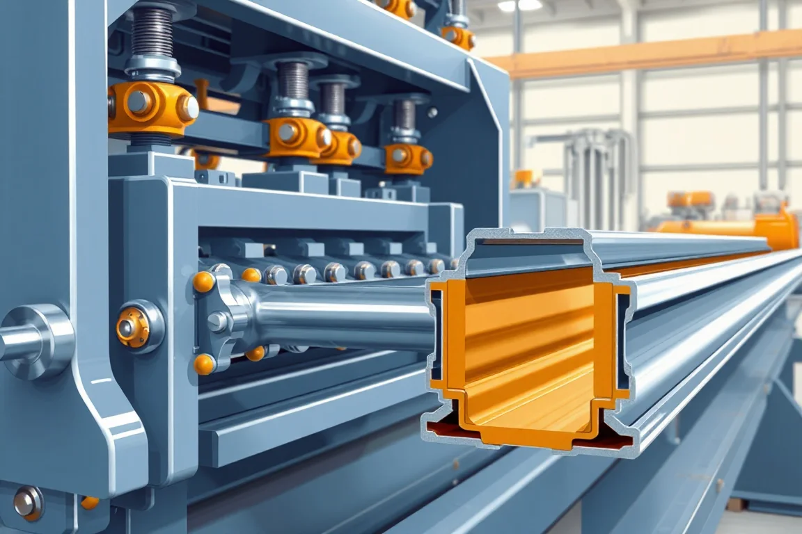
The roller, tooling and forming design of a guardrail roll forming machine is the set of decisions that translates an approved barrier drawing into a repeatable production sequence. It covers the number and arrangement of forming stations, the shape and material of each roll, the strip locating strategy, the punch and cutoff tooling, and the way those elements interface with the specified steel and coating sequence. It does not establish crashworthiness, and it does not by itself make a complete barrier system. A road barrier is a tested assembly of beams, posts, spacers and connections; roll forming produces one or more of those components. This page focuses on the forming and tooling design decisions that determine whether component production matches the drawing.
The practical starting point is the approved barrier drawing and the applicable procurement specification. That drawing defines the beam wave, bolt-slot pattern, lap orientation and post connection geometry. The roll tooling design must reproduce those functional dimensions in the specified material and thickness. A roll count quoted without a forming design does not demonstrate that the line can meet the drawing, because the same nominal profile can be formed in different ways with different tooling interfaces and different sensitivity to material variation.
What the roller and tooling design actually controls
Roll tooling controls the progressive shaping of the strip from a flat or pre-punched blank into the beam section. Each forming station applies a partial bend that contributes to the final wave. The design decides the sequence of those bends, the radius and surface contact at each station, the way the strip is located laterally and vertically, and how springback and material variation are managed across the pass line. It also decides how the formed section is supported through the punch and cutoff operations so that established geometry is not disturbed.
Tooling design therefore connects three things that are often discussed separately: the forming of the wave, the punching of splice holes and other features, and the cutoff that produces the beam length. If punch tooling does not reference the same datums as the forming tooling, splice-hole position can drift relative to the wave even when each operation looks acceptable on its own.
How the forming sequence and tooling interfaces work
A typical sequence begins with leveling or strip preparation, then punching of the splice-hole pattern and any other required features, then progressive beam forming, then cutoff, with coating and assembly operations following as specified. The ordering matters because punching before forming means the holes must be positioned on the flat strip so that they land correctly after the wave develops, while punching after forming requires tooling that can access the formed section without deforming it.
At the forming stations, the strip is located by specific surfaces and shoulders. The design should explain which surfaces establish the strip position at each stage, how the strip is guided between stations, and how the final section is accessed for adjustment or tool change. Springback is addressed by overbending or by designing the final stations to compensate for the elastic recovery of the specified steel. Because material yield and thickness vary within the accepted range, the tooling should account for that variation rather than relying on a single setup point.
The punch and cutoff tooling interface with the forming line through the pass line, the feed and the control of strip position. Confirm profile-supported cutoff, cut lengths, end quality and any secondary operations. A cutoff that does not support the formed profile can distort the wave or the end condition, which then affects lap fit and splice alignment during assembly.
Starting from functional geometry rather than a roll count
The functional geometry of the beam includes the wave shape, the bolt-slot pattern, lap orientation and post connection geometry. These are the dimensions that determine whether the beam will fit the posts and spacers and whether splices will align on site. A roll tooling design should be reviewed against those dimensions first. Cosmetic features and roll counts are secondary to the ability to reproduce the functional section within the accepted tolerance.
W beam and two-wave beam describe the same broad geometry; thrie beam and three-wave beam likewise overlap. Those labels are not a substitute for the approved drawing. Use the drawing to identify genuine differences such as wave depth, flange angles, lap direction and slot position, and translate those differences into tooling requirements.
Material, thickness and coating sequence
The specified barrier-system steel and its base-metal thickness and grade drive the forming loads, the springback behavior and the tooling wear pattern. The coating sequence must be agreed because it affects whether punching and forming happen before or after coating, and whether the tooling must accommodate coated surfaces without marking or damaging them. When coating is applied after forming, the forming design may need to account for dimensional changes; when coated strip is formed, roll surfaces and lubrication strategy may need to protect the coating.
Thickness and grade are buyer-specified inputs. The operating range requires supplier verification, because a line set up for one combination may not produce acceptable geometry across a wider range without tooling changes or additional stations. Keep component dimensional acceptance separate from system crash-testing and installation approval: meeting the drawing is necessary but does not by itself demonstrate in-service performance.
Selection tradeoffs: fixed versus adjustable tooling
One decision is whether the line is dedicated to a single beam profile or intended to cover a family of profiles. A dedicated set of rolls can be optimized for one wave and one material, which can simplify the forming sequence and reduce changeover. A more flexible arrangement may use adjustable or interchangeable tooling, which can cover multiple profiles but adds setup complexity and requires disciplined tool identification so that production does not depend on an undocumented adjustment.
A second tradeoff is the number and distribution of forming stations. More stations can distribute the bend increments more gradually, which can reduce strain localization and improve surface quality, but it increases tooling cost, line length and maintenance scope. Fewer stations can be more compact but may demand larger bend increments that are more sensitive to material variation. The appropriate balance depends on the profile complexity, the specified steel and the accepted output per shift with the actual profile and material.
A third tradeoff is the extent of in-line punching and cutoff integration. Integrated operations can reduce handling and improve datum consistency, but they also couple the forming line to the punch and cutoff tooling, so a change in one area may require requalification of the others.
What to review in a proposed tooling design
Ask how the bends develop station by station, which surfaces locate the strip, how springback is addressed, and how tooling is changed. The design should account for material variation and access to the final section. Review punch and cutoff tooling together with the roll tools, because they share datums and pass-line requirements. The goal is a documented forming concept, not a station count.
Confirm how the accepted setup is recorded and how tooling is identified. Keep the accepted setup and tool identification together so production does not depend on an undocumented adjustment. This is a documentation and control issue as much as a mechanical one, and it affects repeatability across shifts and across tool changes.
Practical checklist for evaluating roller and tooling design
- Identify functional dimensions and mating parts from the approved barrier drawing.
- Confirm the beam wave, bolt-slot pattern, lap orientation and post connection geometry are explicitly addressed.
- Review punch and cutoff tooling together with the roll tools for shared datums.
- Ask how each bend develops and which surfaces locate the strip at each station.
- Confirm how springback and material variation are handled across the specified range.
- Verify tool changes using the agreed material and profile extremes.
- Check access to the final section for adjustment, inspection and maintenance.
- Confirm the accepted setup and tool identification are recorded together.
- Separate component dimensional acceptance from system crash-testing and installation approval.
Acceptance and output considerations
Acceptance of formed components should inspect wave geometry, splice-hole position, lap fit and beam length. These checks relate to the drawing and to the mating parts, and they can be performed on the component before it enters the barrier system. They do not substitute for system-level testing or installation approval.
Accepted output per shift should be defined with the actual profile and material, not as a generic rate. The variables that affect it include the forming sequence, the material grade and thickness, the punch and cutoff cycle, the coating sequence and the handling between operations. A realistic output definition states the profile, the material, the accepted quality criteria and the operating assumptions, so that the figure can be compared across proposals. No verified model rating is implied by a roll count or a station count.
Component production versus assembly, certification and in-service performance
Roll forming produces components. Assembly and installation combine those components with posts, spacers and connections into a barrier system. Certification and crash-testing apply to the system as tested, not to a forming line. In-service performance depends on installation, foundation conditions and maintenance. Keeping these stages separate prevents a forming design from being presented as evidence of barrier performance, and it clarifies which requirements belong in the equipment specification and which belong in the system specification.
FAQ
Does a higher number of forming stations mean better beam quality?
Not by itself. More stations can distribute bend increments more gradually, which can help with surface quality and strain distribution, but quality depends on the forming concept, the roll surfaces, the strip locating strategy and the material. A roll count without a forming design does not demonstrate quality.
How should punch tooling relate to the forming tooling?
Punch tooling must reference the splice datums used by the forming tooling so that hole position remains correct after the wave develops. If the two operations use different datums, splice-hole position can drift relative to the wave. Review punch and cutoff tooling together with the roll tools.
Can one line make the entire barrier system?
Not typically. Posts, beam sections and spacer blocks may need different processes, and a barrier is a tested assembly of multiple components. Roll forming can produce one or more of those components, but it does not establish crashworthiness or installation approval.
What material information is needed before tooling design?
The specified barrier-system steel, base-metal thickness, grade and the coating sequence must be agreed. These inputs drive forming loads, springback behavior and tooling wear. Thickness and grade are buyer-specified, and the operating range requires supplier verification rather than assumption.
How is springback addressed in guardrail roll tooling?
Springback is addressed by designing final stations to compensate for elastic recovery, often through overbending or by shaping the last passes so the section relaxes into the target geometry. Because yield and thickness vary, the design should account for material variation rather than relying on a single setup point.
What should be inspected before accepting formed beams?
Inspect wave geometry, splice-hole position, lap fit and beam length against the approved drawing and mating parts. Keep component dimensional acceptance separate from system crash-testing and installation approval, because they address different risks.
Continue your research
- Guardrail & Crash Barrier Roll Forming Machines
- W Beam Guardrail Roll Forming Machine
- Thrie Beam Guardrail Roll Forming Machine
- Guardrail C Post Roll Forming Machine
- Guardrail Sigma Post Roll Forming Machine
- Guardrail U Post Roll Forming Machine
- How Guardrail roll forming machine Works
- How To Choose a Guardrail roll forming machine
- Guardrail roll forming machine Price: What Affects the Cost?