
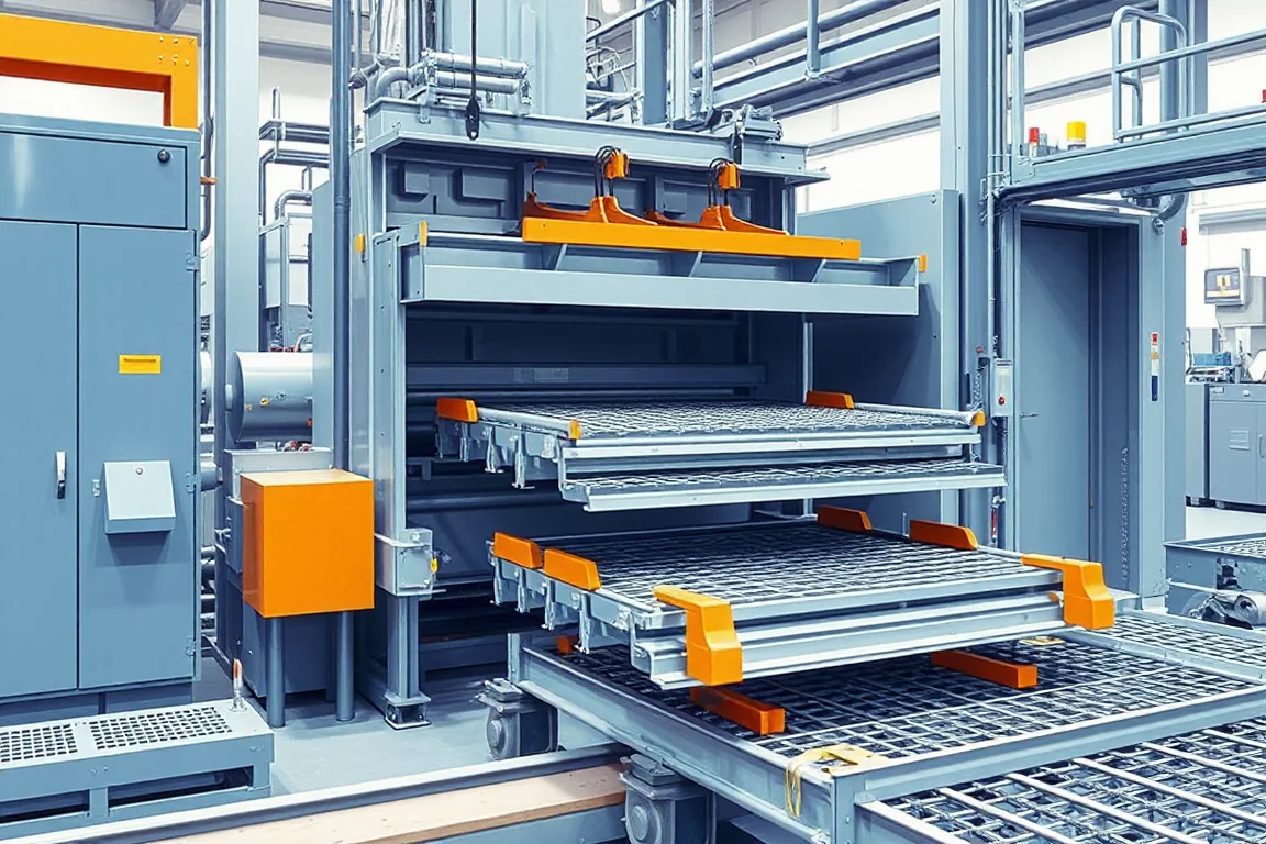
Cable tray production speed is frequently asked as a single figure, but the only meaningful speed is the rate at which the line delivers acceptable finished tray. That rate depends on the profile, the material, the perforation pattern and the reliability of each station. A machine may run quickly on plain channel but slow dramatically when dense holes, long cut lengths or cover-fit features are added. This guide explains how to think about production speed, where it is lost, how to compare alternatives and how to evaluate a quotation without relying on a headline number.
What production speed actually means on a cable tray line
Production speed has three useful layers. First is the steady running speed of the strip through the forming stations. Second is the effective speed once acceleration, deceleration and any stop-start operations are included. Third is accepted output, which is the length or number of good trays produced in a working period after subtracting rejected material, rework and downtime. Buyers who compare only the first layer can be surprised when the second and third layers fall short. A line that runs fast but stops often for punch changes or coil changes will not deliver proportionate output.
Accepted output is the only figure that supports production planning. It depends on the product mix, the cut-length distribution and the hole pattern. Because those vary by order, no single machine rating can describe output across all jobs. The practical approach is to define a representative job and measure the line on that job.
The process sequence and where speed is decided
A typical cable tray line follows a sequence: payoff, leveling, perforation or punching, side forming, cutoff, then cover and assembly checks. The interface between these stages determines the practical speed. The payoff must supply strip smoothly; tension variations can cause the line to hesitate or produce dimensional drift. Leveling sets flatness and can influence how consistently the strip enters the punch and forming stations. Perforation is often the pacing operation because punches must cycle for each hole group. Side forming then shapes the base width, side height and return edge. Cutoff separates the finished length, and cover engagement is checked after forming.
Speed is decided at the slowest mandatory operation. If punching cannot keep pace with forming, the forming stations run below their capability or the line stops intermittently. If cutoff requires a long stroke or a secondary operation, it can impose a cycle limit. Understanding the sequence helps identify which station to investigate first.
Why the punch station is often the bottleneck
Perforated cable tray requires many holes. A dense pattern can force the punch to make multiple hits per advance, and each hit consumes time. The punch may also need to change tools for different patterns, and tool changes interrupt flow. In addition, hole quality matters: material around holes can distort during forming, and inspection around holes is necessary after forming. If the punch station is the pacing item, increasing the speed of downstream stations will not raise accepted output.
Ladder-type tray is a distinct case. Rungs are separate components, and rung production and assembly may sit outside the rail-forming line. A ladder line is not simply a perforated tray line with larger holes; treating it as such leads to unrealistic speed expectations.
Material and thickness effects on speed
Material grade and thickness influence speed in several ways. Thicker or stronger material requires more force to form and punch, which can slow the punch cycle and increase the risk of dimensional variation. Stainless steel and aluminum behave differently from galvanized steel and may require different tooling clearances and lubrication. Surface finish also matters: soft coatings can mark or scratch, encouraging slower handling.
Thickness range requires supplier verification because a machine that forms a thin gauge well may not form a heavy gauge at the same rate. Buyers should specify the intended base-metal thickness and grade so the supplier can confirm the operating range. Speed should be discussed for the specific material and thickness, not as a universal figure.
How to find the actual bottleneck without guessing
Start by observing the line during a representative run. Note which station causes the line to pause, which station requires manual intervention, and where material accumulates or starves. A stopwatch and a simple tally of stoppages can reveal whether the pacing issue is punching, cutoff, coil changes or unloading. Look for evidence rather than assumptions: if the punch is idle while forming waits, the bottleneck is upstream; if formed tray accumulates before cutoff, the bottleneck is cutoff.
It is not necessary to adjust moving machinery to diagnose. Observation of timing, queue formation and operator actions is enough to identify the limiting station. Any adjustment should be performed by qualified personnel following the manufacturer's procedures.
How to estimate accepted output for planning
A simple planning model is accepted length equals steady running speed multiplied by actual running minutes multiplied by good-output fraction. For example, if the line runs at a steady rate and the available running minutes are known, the product gives a rough length. This is an arithmetic illustration, not a machine specification. The number of cut lengths is obtained by dividing total accepted length by the representative cut length, but only when the cut-length mix is uniform and the cutoff cycle does not add delay.
Actual running minutes must exclude coil changes, setup, punch changes and unloading. Good-output fraction must reflect measured reject and rework rates for the intended profile and pattern. These inputs are best gathered from a trial with the actual material and hole pattern. Without that trial, estimates remain generous.
Checklist for evaluating production speed claims
- Define a representative profile, material, thickness and cut length before discussion.
- Ask for a demonstration using the intended perforation pattern, not a simplified sample.
- Measure running minutes over a realistic period that includes coil changes and normal stoppages.
- Count rejected and reworked parts separately.
- Record the hole pattern and cut-length mix; note any tool changes required.
- Confirm which station paced the line during the demonstration.
- Verify base width, side height, burr condition and cover engagement on finished parts.
- Inspect around holes after forming because perforated parts can distort.
- Check whether ladder rungs are produced on the same line or separately.
- Review the equipment schedule for installed power and site services; do not infer it from a speed claim.
Comparing alternatives for higher output
When output is insufficient, buyers consider several directions. One is a dedicated high-capacity punch station with faster cycling or multi-hole tooling. Another is a separate punching operation offline, which can simplify the forming line but adds material handling. A third is a line with more forming stations to reduce per-station load and improve consistency, which may allow higher running speed but increases floor space and cost. A fourth is a different tray type, such as ladder tray, if the application permits.
Each alternative trades capital, floor space, tooling complexity and flexibility. A higher-speed line may be less tolerant of short runs or frequent pattern changes. An offline punch may reduce line complexity but increase work-in-progress. The right choice depends on the product mix and the cost of a bottleneck hour.
Cost and quotation scope for speed-related features
Production speed affects cost through the equipment required to achieve it. A quotation should state whether the offered line includes the punch tooling for the intended pattern, the cutoff arrangement, the leveling section and the payoff. Speed-related cost appears in the punch capacity, the number of forming stations, the drive system and the control architecture. Without a confirmed equipment schedule, installed power and utility requirements cannot be compared.
Accepted-output cost is the total cost of ownership divided by good output over a period. That includes material yield, tooling life, labor, maintenance and downtime. A lower-priced machine that produces more scrap or stops more often may cost more per accepted tray. Buyers should ask for the scope of supply and the assumptions behind any output figure, rather than treating a single speed number as a price justification. No prices are provided here because they depend on configuration and market conditions.
Distinguishing speed from quality and certification
High output does not imply a compliant tray. Base width, side height and return edge must meet the specified profile, and burr condition must be acceptable for handling and coating. Cover engagement must be checked on assembled sections. Perforated parts require inspection around holes after forming because the forming operation can distort the hole edge. Load rating and electrical continuity depend on the complete system and its verification, not on the forming line alone.
Certification and in-service performance are separate from production speed. A line can produce quickly and still require a separate qualification of the finished tray for the intended installation. Buyers should keep these topics distinct when comparing suppliers and planning output.
Maintenance and setup factors that limit real output
Tooling wear, roll alignment and lubrication affect the sustainable speed. A line that runs quickly when new may slow as tools dull or as alignment drifts. Setup time for a new profile or hole pattern also reduces effective output. Coil changes are another predictable interruption. Planning should include time for these activities and should not assume that nominal shift minutes are all running minutes.
Maintenance and troubleshooting procedures should follow the manufacturer's instructions. Operators should not adjust moving machinery without training and authorization. The goal here is to identify where output is lost so that the right maintenance or process change can be discussed.
FAQ
Can a cable tray roll forming machine run at one stated speed for all profiles?
No single speed applies to all profiles. Speed depends on the width, side height, return edge, hole pattern, material and cut length. A line may run at one rate on a plain channel and a lower rate on a densely perforated tray. The realistic figure is the accepted output for a specific job.
Why does perforation reduce production speed more than forming?
Perforation often requires multiple punch cycles per advance, and each cycle takes time. Dense patterns increase the number of hits, and tool changes interrupt flow. Since the punch is a pacing operation, forming stations downstream cannot compensate if the punch is the slowest mandatory step.
How should a buyer measure accepted output during a demonstration?
Run the intended profile, material and hole pattern. Record actual running minutes, count good parts, and separately count rejects and rework. Note stoppages for coil changes, punch changes and unloading. Then calculate accepted output for the demonstration period. This measurement is more useful than a catalog speed.
Does a higher running speed always mean lower cost per tray?
Not necessarily. If the higher speed comes with more scrap, longer setup or higher tooling cost, the cost per accepted tray can rise. Cost per accepted tray includes material yield, labor, maintenance and downtime. The equipment price alone does not determine it.
How does ladder tray production differ from perforated tray production?
Ladder tray uses separate rungs and rails. Rung production and assembly may occur outside the rail-forming line, so the line speed for rails does not represent finished ladder output. Perforated tray, by contrast, is formed as a continuous profile with holes in the base or sides.
What information should a supplier provide to support a speed claim?
A responsible claim should state the profile, material, thickness, hole pattern, cut length and the measurement method used. It should distinguish steady running speed from accepted output and identify any assumptions about coil changes and setup. Without this scope, a speed number is not actionable for planning.
Bringing the decision together
Production speed is best treated as a system property. The profile, material and hole pattern set the demand; the sequence of stations sets the constraint; and the accepted output measured on a representative job sets the planning basis. Buyers who define the job, observe the line, count good and bad output, and compare alternatives on cost per accepted tray will make a decision that holds up in production. The FAQ answers above address the most common questions directly, and the checklist provides a structured way to compare suppliers without relying on a headline speed.
Continue your research
- Cable Tray Roll Forming Machines
- Cable Tray Roll Forming Machine
- Cable Ladder Roll Forming Machine
- Solid Bottom Cable Tray Roll Forming Machine
- U Channel Cable Tray Roll Forming Machine
- Cable Support Channel Roll Forming Machine
- How Cable tray roll forming machine Works
- How To Choose a Cable tray roll forming machine
- Cable tray roll forming machine Price: What Affects the Cost?