
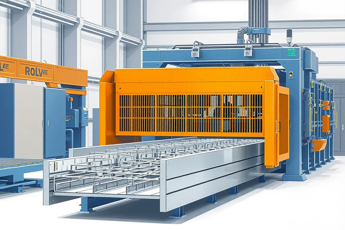
A cable ladder roll forming machine makes the side rails or rung profiles used in a specified ladder-type cable-support assembly. A complete ladder contains two rails connected by repeated rungs, so the manufacturing project must address component production, feature accuracy and the joining process that turns loose profiles into finished sections.
This is different from forming a perforated tray from one wide strip. The ladder's useful dimensions depend on the relationship between separate parts. Selecting equipment only from a photograph of the finished ladder can leave the most important assembly operations outside the quoted scope.
Which components does the proposed machine make?
Identify whether the proposal covers side rails, rungs or both. Each can have a distinct cross-section, material width and feature schedule. A rail former should not be described as a complete ladder line unless the remaining components and assembly operations are also defined.
Specify the finished ladder family, including width, rail height, section length and rung spacing. Then map those dimensions to the component drawings. This makes it clear which changes require a different rail, which require a different rung length and which affect assembly tooling.
How should side-rail geometry be defined?
Provide the rail section with its web, flanges, returns and any lid-engagement or splice features. Identify the inside face and the surfaces that locate rungs. Rail orientation matters when the two sides are handed or contain asymmetric features.
- Rail height and complete cross-section.
- Rung connection details and feature datums.
- Splice holes and end relationships.
- Optional cover or divider interfaces.
- Material grade, thickness and finish.
- Finished rail length, straightness and end condition.
Do not assume that two rails with similar outside dimensions accept the same rung or splice. The functional connection surfaces should guide the tooling and inspection plan.
What must be specified for the rungs?
The rung drawing defines the cable-supporting face, cross-section, cut length and end interface. It may include holes or other features associated with the selected cable-support system. Those details need a separate manufacturing review from the side rail.
Rung length and ladder width are related but are not necessarily the same measurement. The connection can overlap, insert into or attach against the rail according to the design. Define the finished assembly width and the corresponding component dimensions explicitly.
Where several widths share one rung profile, evaluate the length-change and sorting process. Rungs of nearby lengths can be mixed easily, so identification and assembly feeding should be considered before choosing collection equipment.
How does component production connect to assembly?
- Produce and inspect the specified side-rail profiles.
- Produce and inspect rungs with the required lengths and end details.
- Prepare rails and rungs in the correct orientation.
- Locate them in the assembly arrangement at the required spacing.
- Join them using the approved method.
- Inspect the complete ladder, then finish and pack it as specified.
The joining method can involve welding or mechanical connections according to the product design. The equipment scope should state the actual method, fixtures and inspection responsibilities. It should not assume that any attachment which holds a demonstration together is suitable for production.
What determines rung-position accuracy?
The finished rung spacing depends on feature references, fixture location and joining control. If rails contain prepunched locating or attachment holes, their position must remain correct after forming and cutting. If the fixture establishes spacing independently, its references and adjustment method need clear definition.
Inspect several consecutive rungs and their relationship to the ladder ends. A single correct spacing does not establish the cumulative layout. Check the orientation of cable-supporting faces and any required openings as well as their center positions.
Record whether a deviation originates in the rail features, rung length, fixture or joining stage. Correcting the wrong component can make a selected sample fit while creating inconsistency across later assemblies.
How should material and finishing be planned?
Specify materials for rails and rungs separately, including grade or alloy, thickness and surface condition. They may have different dimensions and forming demands even when the finished ladder uses one nominal material family.
Define whether the assembly is finished before or after joining and which operations are required by the selected coating route. Joining can affect local finish, and later processing can affect appearance or geometry. The final inspection should address the completed product after its specified manufacturing stages.
Retain material and production identification through component storage and assembly. A ladder made from mixed unrecorded rail or rung batches can be difficult to investigate if a later quality issue appears.
What does width adjustment involve?
For many ladder families, width variation changes rung length and assembly-fixture spacing while the side-rail section remains the same. Other catalogues also change rail height or geometry. Distinguish those cases before asking for automatic width change.
Demonstrate a complete transition: correct rungs, fixture position, rail features, joining settings and final width inspection. A quick movement of the assembly rails does not prove that all required component and process changes have occurred.
If one forming system alternates rail and rung profiles, include its tool changes and scheduling in the comparison. Separate component lines can simplify simultaneous supply, while shared equipment may suit a different volume and order mix.
How should splice and cover fit be checked?
Join representative finished ladder sections with their specified couplers. Check rail alignment, hole position and the condition of the ends. The assembly should not depend on spreading rails or modifying holes to overcome a manufacturing mismatch.
Where a cover is included, test its attachment on completed ladders rather than loose rails alone. Joining may change the relationship between the rails, so an acceptable component fit does not automatically prove the final assembly fit.
Keep those mechanical checks separate from the system's load, electrical continuity or other required performance verification. The relevant design and test plan should assign those responsibilities explicitly.
What should the layout provide for component flow?
Provide separate, identifiable storage for rails and rungs, then a controlled route into assembly. Similar rung lengths should not be mixed. Include space for finished ladders, inspection, rejected parts and any downstream finishing.
Handling should support complete sections without introducing twist or damaging rung joints. Define stack orientation and separation where required. A line trial should follow the product through normal movement rather than stopping at the joining fixture.
How should production capacity be evaluated?
Use accepted complete ladder sections for a stated size, material, rung pattern and joining method. Rail forming, rung manufacture, assembly, joining and inspection can each limit the result. Reporting only the side-rail speed gives an incomplete picture.
For a planning example, a batch of 100 ladders containing 12 rungs each requires 1,200 accepted rungs plus 200 accepted side rails. Those figures illustrate component balance, not a universal ladder design. Use the actual drawing and bill of materials for the project.
Compare quotations by separating component equipment, fixtures, joining, controls, finishing and packing. Identify any manual work and its staffing assumptions so different automation levels can be evaluated fairly.
What should acceptance demonstrate?
- Rail and rung dimensions in the specified materials.
- Feature locations, end condition and correct component orientation.
- Finished ladder width, rung spacing and alignment.
- Joining quality according to the approved process.
- Splice and cover fit where included.
- Required size changes and recovered production.
- Accepted complete sections after normal handling and packing.
Retain component and assembly references together. A complete record helps locate future deviations instead of attributing every ladder problem to the rail former.
Frequently asked questions
Is a cable ladder made like a perforated tray?
No. A ladder is assembled from side rails and rungs, while a sheet tray follows a different construction. The component and joining routes must be included when selecting ladder equipment.
Does the machine include rung welding?
Only if the specified ladder uses welding and that equipment is included. Other designs use different connections. Define the joining method, fixtures and inspection rather than assuming it from the product name.
Can ladder width change without new rail tools?
It may where the same rail section is retained and width changes through rung length and assembly spacing. Confirm the actual family and demonstrate the full transition, including component identification and final inspection.
Why inspect the completed ladder?
Joining combines separate tolerances and can alter alignment. Correct loose rails and rungs do not automatically guarantee the final width, spacing or splice fit. Assembly inspection addresses that additional production stage.
What limits practical output?
The slowest required component, joining or handling stage can constrain complete ladders. Measure accepted assemblies for the real product mix rather than quoting the fastest individual machine in isolation.
What should an enquiry include?
Provide rail, rung and assembly drawings, materials, joining method, widths, lengths and rung patterns. Add splice, cover and finishing requirements. This defines the complete ladder-manufacturing route and its equipment boundaries.

Continue your research
- Cable Tray Roll Forming Machines
- Cable Tray Roll Forming Machine
- Cable Trunking Roll Forming Machine
- Solid Bottom Cable Tray Roll Forming Machine
- U Channel Cable Tray Roll Forming Machine
- Cable Support Channel Roll Forming Machine
- How Cable tray roll forming machine Works
- How To Choose a Cable tray roll forming machine
- Cable tray roll forming machine Price: What Affects the Cost?
Configuration & specification inputs
Match the configuration to your section drawing, material and production requirements.
| Parameter | Requirement / confirmation needed |
|---|---|
| Profile geometry | Defined side rails and rungs with their complete joining interfaces |
| Material | Rail and rung specifications tracked separately through assembly and finishing |
| Thickness & grade | Component-specific grade, thickness and strip-width requirements |
| Process route | Rail and rung manufacture, orientation and location, approved joining, final inspection and packing |
| Cutting | Coordinate rung length, rail ends and splice features with assembled dimensions |
| Output | Accepted complete ladder sections for the stated rung pattern and joining method |
| Electrical supply | Confirm utilities for all component lines, fixtures, joining and collection equipment |
| Acceptance | Check rails and rungs, assembled width and spacing, joints, splices and cover fit |