
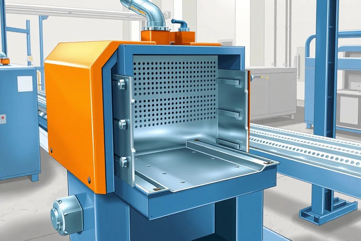
A width adjustable cable tray roll forming machine is intended to produce several approved tray widths on one route. The useful capability is not simply moving the side-forming units farther apart. The tray must retain the correct side profile, feature positions, cover fit and connection geometry at every approved width.
The equipment brief should therefore start with a size matrix and realistic order sequence. A family with one side height and several base widths is different from a catalogue that also changes height, top returns, material and perforation patterns.
Which dimensions should vary?
List base width, side height, edge return and material combinations separately. Identify which products share the same side profile. State internal usable width and outside width with their measurement conventions.
Ask the supplier to mark supported adjustments, required tool changes and excluded combinations. A broad width range should not be treated as evidence that every side height or cover design can be made without additional tools.
How does input-strip width relate to tray width?
The flat strip supplies the base, both sidewalls and the top-edge details. Different base widths usually change the developed input requirement unless another explicitly designed process is used. Confirm coil specifications for every approved tray.
Include coil changes in production planning. An automatic forming-width movement may be quick while changing the material supply takes longer. State clearly whether quoted changeover times include that work.
What must happen to punching positions?
Base perforations, side features and connection holes must remain correctly positioned when width changes. The proposal should explain which punch locations adjust, which tools change and which patterns are selected through programs.
- Define feature datums on the finished tray.
- Keep end-coupling holes registered to cut length.
- Show solid margins near bends and ends.
- Identify width-specific perforation patterns.
- Verify the first featured tray after each meaningful change.
A correct outside width does not prove that the feature program followed the adjustment. Final-part checks need to cover both functions.
How should side profiles remain consistent?
The side-forming arrangement must recover the approved height, angle and top return at each width. The wider base can also change handling behavior. Trial several sizes rather than approving the family from one mid-width sample.
Measure the tray in an agreed support condition without forcing the base flat or sides square. Check twist and straightness separately from local return dimensions. This reveals the actual delivered shape.
What changes are needed at cutoff and discharge?
The cutting arrangement must accommodate the full tray and preserve both side edges. Ask whether support or tools change with width. The takeoff should handle narrow and wide products without local damage or unstable transfer.
Review the package format for each size. A stack arrangement suitable for narrow trays may not support a wide base adequately. Demonstrate normal bundling as part of the width-range trial.
How should covers and couplers be included?
Use width-matched covers and connection references. The tray's top return and end features need to fit these accessories after every relevant change. A common nominal width does not guarantee a common retention or coupling interface.
Identify cover and fitting manufacture separately. The adjustable tray line may make straight bodies only, while covers, bends, tees and reducers use other equipment. Their interfaces still belong in the product review.
How can changeover be measured usefully?
Measure from the last accepted old tray to the first accepted new tray, including the required coil, guides, punch settings, cutting support and inspection. Record excluded tasks explicitly. Test a representative transition, not only the easiest width movement.
For a mixed order book, compare accepted output over the full schedule. A slightly slower steady line can still perform well if it reliably reduces complete changeover work; the trial should show the actual balance.
How should approved settings be recorded?
Keep each tray recipe linked to the drawing, material, input width and required physical tools. Record the inspection sample used to approve it. This makes a later repeat order easier to verify and avoids treating a stored width value as a complete manufacturing setup.
What should the range-acceptance plan contain?
- The complete size, material and pattern matrix.
- Representative narrow, wide and normal products.
- Final width, side geometry and feature measurements.
- Cover and coupler fit at each selected size.
- Cutoff and package-condition checks.
- Complete width-change timings and startup scrap.
- Accepted mixed-order output with clear scope.
Keep product loading, electrical continuity and application assessments separate from dimensional range acceptance. The machine's width flexibility does not establish those system properties.
Frequently asked questions
Does width adjustment also change side height?
Not necessarily. They are separate capabilities. Provide the actual size matrix and ask which height changes require different tools or settings.
Can one coil width make every tray width?
Do not assume that. The developed strip must supply the base and sides. Confirm the input requirement for each approved product and include material changes in planning.
Will punching move automatically with the sides?
Only if the proposed feature equipment supports that coordination. Verify final hole and slot positions after the width change.
What is the right changeover endpoint?
The first complete accepted tray with correct features and accessory fit. Timing only the movement of the side-forming units leaves important work unmeasured.
What should a buyer provide first?
Send the size and material matrix, perforation patterns, covers, couplers, lengths and a typical order sequence. That lets suppliers propose flexibility around actual production needs.
Buy a repeatable tray family, not movement alone
A useful adjustable-width line preserves the whole tray product across sizes. Linking forming, punching, cutting and accessory fit makes that flexibility measurable and easier to compare.

Continue your research
- Cable Tray Roll Forming Machines
- Cable Tray Roll Forming Machine
- Cable Ladder Roll Forming Machine
- Solid Bottom Cable Tray Roll Forming Machine
- U Channel Cable Tray Roll Forming Machine
- Cable Support Channel Roll Forming Machine
- How Cable tray roll forming machine Works
- How To Choose a Cable tray roll forming machine
- Cable tray roll forming machine Price: What Affects the Cost?
Configuration & specification inputs
Match the configuration to your section drawing, material and production requirements.
| Parameter | Requirement / confirmation needed |
|---|---|
| Profile geometry | Approved tray size matrix separating variable base width from side height and top-edge geometry. |
| Material | Recipe-specific grade, coating and developed input strip for each tray variant. |
| Thickness & grade | Reviewed material-thickness combinations across narrow, wide and normal products. |
| Process route | Coordinated material and tooling selection, registered features, width-adjusted forming, cutting and packaging. |
| Cutting | Width-appropriate support with preserved side edges and end-coupling registration. |
| Output | Accepted mixed-width orders including complete transitions, inspection and startup waste. |
| Electrical supply | Utilities for adjustable forming, coordinated punching, cutoff and handling equipment. |
| Acceptance | Width, sides, patterns, covers, couplers, package condition and repeatable approved recipes. |