
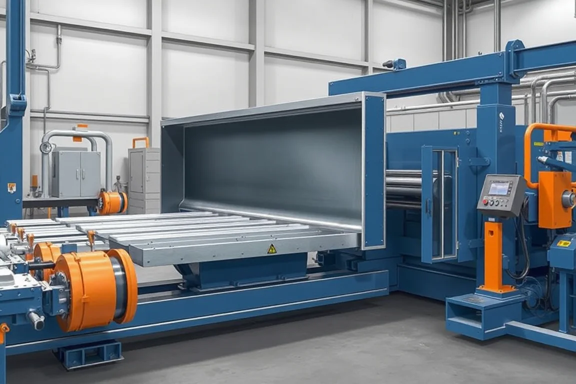
A trailer side wall post is not a simple trim strip. It is a structural member that ties the side panel, roof rail and floor structure together. The profile carries vertical, lateral and torsion loads; its flanges receive fasteners, its faces bond or rivet to panels, and its ends engage roof and floor rails. That functional role dictates the geometry, the material, the processing route and the way the finished part should be inspected.
This article covers the dedicated roll forming machine for trailer side wall posts. It distinguishes the forming route from assembly and certification, explains what to define before tooling approval, and gives practical guidance for specification, acceptance and quotation scope. The supplied application notes—interface requirements, material and thickness definition, process route, cutoff needs, output targets, power supply and acceptance checks—are treated as selection requirements, not as verified machine specifications.
What a Trailer Side Wall Post Does
A side wall post runs from the floor structure to the roof rail. It stiffens the side panel, resists panel panting, participates in the trailer's global bending and torsion behaviour, and provides the attachment plane for interior linings, exterior skins, tie-downs and lighting harnesses. Because it is a structural element, the drawing normally controls the section geometry, the datum scheme, the hole pattern, the joining flanges and the assembly interfaces.
Selecting a post solely by section height is a common error. Two posts with the same nominal height can have very different second-moment behaviour, different fastener edge distances and different panel-bonding areas. The useful question is what the post connects to, at what spacing, with what fastener or adhesive, and under what load and durability requirements. Those answers come from the trailer's system-level design, not from the roll forming line.
Drawing and Material Inputs Before Tooling Approval
The controlled part drawing defines the formed section, the bend radii, the flange widths and angles, the hole positions and sizes, and any end preparation. Datums and tolerance callouts deserve particular attention because they determine whether the roll formed part is accepted. If the drawing datums do not match the post's assembly location, the inspection can reject useful parts or accept parts that will not fit.
The material specification is equally important. The drawing-specified automotive steel or other validated alloy defines the grade, yield and tensile strength, coating, and allowable thickness variation. Grade and strength influence the required bend radii, the pass development and springback compensation. A high-strength micro-alloyed grade may form acceptably but spring back differently in each pass, so trial evidence on the actual grade and thickness is a better guide than a generic width or thickness capacity. Thickness and grade are buyer-defined inputs; the operating range for any given machine requires supplier verification on the actual profile and material.
How the Roll Forming Process Route Works
The typical route for side wall posts is traceable coil feed, precision forming, feature and cut operations, joining where applicable, then dimensional verification. Each step has distinct requirements that should be reviewed separately.
- Coil feed and tracking must handle the specified coil width, thickness and grade without marking the coated surface. Strip guidance and loop control affect whether the formed section stays on the intended datum line.
- Forming passes develop the bend sequence. The number and arrangement of passes depend on the section complexity, material strength and acceptable strain at each bend. Simulation or physical trials can show whether a critical feature is reachable and whether the material will crack or distort.
- Feature and cut operations include punching, drilling or notching for fasteners and wiring, plus cutting to length. The cutoff method must suit the profile: a profile-supported cut helps maintain end squareness, and secondary operations such as end shaping or deburring may be required.
- Joining may be integrated as welding, adhesive bonding or riveting, or it may be a separate downstream operation. Where it is integrated, the machine scope should state how the joint is made, how it is monitored and how it is inspected.
- Dimensional verification confirms the section and feature positions against agreed datums. Verification is an ongoing process, not a one-time event at the end of the line.
Where Forming Ends and Assembly Begins
A roll forming machine produces a formed and cut post. It does not make a completed side wall. Assembly includes attaching the post to panels and rails, applying sealant or adhesive, inserting fasteners, and completing any corrosion protection. Those operations may be manual, semi-automated or fully automated, and they are normally outside the roll forming line's scope unless the buyer explicitly integrates them.
Keeping the boundary clear matters for two reasons. First, the line's output is a part, not a finished wall. Cycle time and acceptance calculations should count formed parts, not assembled walls. Second, joining and corrosion protection interact with the forming process: a coating damaged during forming may need repair before assembly, and a tight bend radius may affect adhesive bond-line quality. The mechanical scope should name which of these steps the machine performs and which the buyer performs elsewhere.
Choosing Between Dedicated and Flexible Production Routes
There is no single correct route for all side wall posts. A dedicated line, a flexible line with changeable tooling, and a general-purpose roll former with secondary press work each suit different situations.
- Dedicated line suits a stable, high-volume post family with a controlled drawing revision. Tooling and handling can be optimised for that section, and operator intervention can be reduced. The trade-off is changeover effort when the design changes.
- Flexible line with changeable cassettes or adjustable passes suits multiple post variants, mixed-model production or frequent design iterations. Setup time, setup scrap and tool storage become important evaluation factors.
- General-purpose roll former plus secondary operations can form simple sections and rely on press work for holes and end features. This reduces forming tooling complexity but adds handling, potential datum loss between operations and extra inspection steps.
The comparison should be made on the actual post drawing and material, not on a simplified demonstration section. A route that performs well on a soft, simple profile may behave differently on a high-strength post with several bends and close-tolerance holes.
Cutoff, End Quality and Secondary Operations
Cutoff is where the formed section is separated into parts. The chosen method should be compatible with the profile shape and the required end quality. Some sections need a supported cut to avoid collapse or distortion at the cut plane; others can be cut with a simpler shear or saw arrangement. The cut length, end squareness and any burr condition should be agreed before tooling approval.
Secondary operations are part of the total route. Drilling, punching, notching, end milling or deburring may be required so that the post assembles to the panel or rail. These operations should be listed explicitly in the equipment scope, with the acceptance criteria for each feature. A machine that forms an accurate section but leaves a poor end may still fail at assembly.
Inspection and Acceptance Planning
Inspection should follow a written plan agreed before tooling approval. The plan names the datums, the measurement method, the gauges or fixtures, the sampling frequency and the acceptance criteria. Where possible, it should distinguish first-off inspection from steady-production sampling.
Because the post is a system-level component, inspection includes more than the formed section. Representative panels and fasteners should be trialled on the finished post to confirm that hole positions, flange angles and end conditions actually assemble. Drilling, punching or end preparation should be included in the acceptance route rather than treated as a later detail. The trailer's load and durability requirements are design inputs to that system-level validation, and they define the context in which the post must function.
Output, Changeover and Quotation Scope
A production target should be stated as accepted output per shift with the actual profile and material. Accepted output counts only parts that pass inspection; it also accounts for setup time, changeover steps, startup scrap and any downstream operations. An isolated no-load speed does not represent realistic output.
Quotation scope deserves the same care. Tool development, forming trials, gauges, joining equipment, punching and cutoff tooling, and qualification support can each be substantial scope items. The written scope should separate production hardware from part-validation responsibilities so that the buyer knows what evidence the supplier will provide and what the buyer must validate independently.
Corrosion and Coating Considerations
Trailer side wall posts are often coated or formed from coated stock. The coating protects the formed part and, in many designs, contributes to the panel interface. Forming can abrade or micro-crack the coating at tight bends, so the drawing and the process should define the minimum bend radii that preserve coating integrity for the chosen material.
Cut edges, punched holes and any welded or riveted joints are potential corrosion sites. The inspection plan and the assembly route should state how these areas are protected, whether by sealant, coating repair or design detailing that keeps moisture away. These are system-level decisions, but the forming process affects how easily they can be achieved.
FAQ
Can one roll forming machine produce every trailer side wall post variant?
Not necessarily. Different post variants may have different section widths, bend sequences, hole patterns or material grades. A machine designed for one profile family may require tool changes, additional passes or a different cutoff arrangement for another family. The realistic question is which variants belong to a single controlled part family and which should be treated as separate production routes.
How should thickness and grade be defined before request for quotation?
The buyer should specify the base-metal thickness and grade from the controlled drawing, including the allowable thickness variation and the coating. The supplier then verifies whether the proposed line can form that combination and defines the operating range in writing. The machine's practical range should be confirmed by trial on the actual material, not inferred from a generic capacity statement.
What cutoff information is needed before tooling approval?
The buyer should confirm the cut length, the required end squareness and finish, and whether the cutoff must be profile-supported. Any secondary end preparation, such as drilling, notching or deburring, should be identified at this stage. These details determine the cutoff tool design and whether the operation belongs in the line or downstream.
Should joining be integrated into the roll forming line?
Integration can reduce handling and improve datum consistency, but it also adds complexity, monitoring and maintenance. Whether to integrate depends on the joint type, the production volume, the tolerance chain and the buyer's process capability. The scope should state clearly whether joining is performed in line or after forming.
What electrical supply information should be supplied?
The buyer should state the site voltage, frequency and phase, and provide a confirmed equipment schedule for installed power where that information is available. Power requirements depend on the actual machine configuration, so they cannot be assumed from the profile alone.
What acceptance checks are appropriate for a finished post?
Acceptance checks should cover the formed section against agreed datums, feature positions, cut length and end condition. They should also include a practical assembly check with representative panels and fasteners. The trailer's load and durability requirements remain system-level design inputs that inform how the post is validated in the finished wall.
Practical Checklist Before Approving a Production Line
- Confirm the controlled part drawing, datums and tolerance scheme.
- State material grade, thickness, coating and allowable variation.
- Define the process route from coil feed through dimensional verification.
- Specify cutoff length, end quality and any secondary end operations.
- Decide which joining operations are in line and which are separate.
- Agree the inspection plan, gauges and sampling method before tooling approval.
- Calculate output as accepted parts per shift with the actual profile.
- Record changeover steps, setup scrap and unloading time.
- Run the agreed material and profile, not an easier demonstration substitute.
- Inspect first-off and a representative steady-production sample.
- Compare the written equipment scope with all secondary operations needed for a finished part.
Distinguishing This Application from Adjacent Profiles
Trailer side wall posts differ from several neighbouring automotive profiles. Seat rails and window guide channels prioritise sliding interfaces, surface finish and close tolerances, and their forming and inspection demands follow from those functions. Heavy truck side members are larger structural sections with their own handling and straightening requirements. EV battery tray frames emphasise enclosure interfaces and joining. A trailer side wall post is defined by its panel-and-rail interfaces, its structural role in the wall, and its corrosion and fastener requirements. Those differences should shape the drawing review, the process route and the acceptance plan rather than being treated as interchangeable roll forming jobs.

Continue your research
- Automotive Roll Forming Machines
- Automotive Bumper Beam Roll Forming Machine
- Automotive Door Beam Roll Forming Machine
- Automotive Seat Rail Roll Forming Machine
- Automotive Window Guide Channel Roll Forming Machine
- Heavy Truck Side Member Roll Forming Machine
- How Automotive roll forming machine Works
- How To Choose a Automotive roll forming machine
- Automotive roll forming machine Price: What Affects the Cost?
Configuration & specification inputs
Match the configuration to your section drawing, material and production requirements.
| Parameter | Requirement / confirmation needed |
|---|---|
| Profile geometry | Trailer wall posts need interfaces to panels, roof rails and floor structure. Provide connection details and corrosion requirements instead of selecting a section solely by height. |
| Material | Drawing-specified automotive steel or other validated alloy |
| Thickness & grade | Buyer to specify base-metal thickness and grade; operating range requires supplier verification. |
| Process route | Traceable coil feed → precision forming → feature/cut operations → joining → dimensional verification |
| Cutting | Confirm profile-supported cutoff, cut lengths, end quality and any secondary operations. |
| Output | Define accepted output per shift with the actual profile and material. |
| Electrical supply | Buyer to state voltage / frequency / phase. Installed power requires a confirmed equipment schedule. |
| Acceptance | Trial representative panels and fasteners on the finished post. Include drilling, punching or end preparation in the route. The trailer's load and durability requirements are system-level design inputs. |