
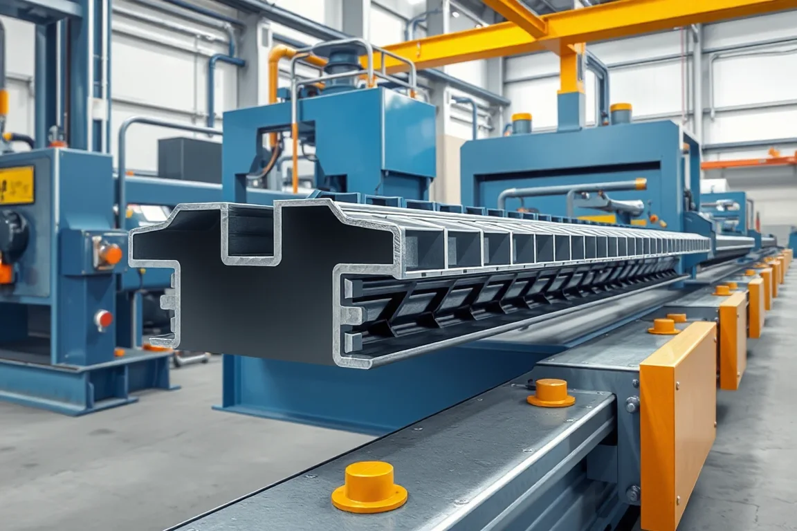
A 2 inch composite deck roll forming machine makes the steel deck component of a specified composite floor system, with a nominal deck depth of 50.8 mm. The complete product includes rib geometry, side laps and engineered surface features where required. The equipment must reproduce that defined profile rather than simply form a two-inch-deep corrugation.
Composite deck is distinguished from plain form deck by its intended role in the qualified deck-slab system. The machinery manufactures the steel component; it does not establish composite behavior merely by adding an arbitrary embossment pattern. Product design and testing remain essential parts of the project.
Which composite-deck geometry must be specified?
Provide rib depth, pitch, crest and valley widths, web angles, side laps and any re-entrant features. Include the approved embossment or deformation pattern, with its dimensions and location on the section. Effective cover and input-strip width should be separate entries.
The drawing should identify the exact product revision used for qualification. A small change to ribs or surface features should not be treated as harmless simply because nominal depth remains two inches.
How does the steel component relate to the slab system?
The selected floor design establishes the concrete, reinforcement, support and other assembly requirements. The roll-forming brief should reference the controlled steel-deck geometry and material needed by that system. It should not invent slab capacities or construction spans.
Keep manufacturing checks and system testing distinct. Accurate deck formation is a necessary product requirement, but it is not a substitute for the engineering and verification applicable to the complete composite assembly.
What makes embossment specification important?
Embossments or other deformations are deliberate features, not decorative texture. Their shape, depth, orientation and registration should follow the approved product drawing. The equipment proposal must identify how they are produced and checked.
- Define the feature pattern on each relevant surface.
- Show its relationship to ribs and bend zones.
- State feature dimensions and inspection references.
- Identify required start and end conditions.
- Include the actual feature process in material trials.
A smooth-sheet trial does not establish the quality of a deck whose working product includes deformations. The complete featured section should be used for acceptance.
How should forming and embossing be coordinated?
The proposed route should explain the sequence of feature creation and profile development. It must preserve the required deformation while producing the final rib geometry. Coil preparation, tools and material behavior should be considered together.
Inspect the feature after the entire forming route rather than only immediately after the embossing station. Subsequent contact or bending can affect its delivered condition. The final deck is the product that needs approval.
Which materials should be included in the matrix?
Pair steel grade, base-metal thickness and coating with the approved section. Include incoming-strip requirements and retain coil identity during trials. Different grades or thicknesses may affect both rib formation and the surface-feature result.
Choose representative normal and demanding combinations. Do not combine separate maximum thickness and maximum strength statements into an unreviewed capability claim. The equipment envelope should be tied to actual product cases.
What should cutoff and side-lap trials prove?
Check rib and lap geometry at the cut ends, end squareness and local distortion. Join sheets using the intended side-lap arrangement and measure effective cover. Inspect feature condition near the ends where the process requires it.
Use representative lengths and the normal discharge route. Deeper ribs and featured surfaces need suitable support during transfer and stacking. The package should not crush laps or damage the accepted deformation pattern.
Can the same line make other composite depths?
Only through an explicit tooling and product review. A move from two-inch to another depth can change rib geometry, material development, embossments and cutoff requirements. The side lap may also differ.
Request a complete variant matrix and demonstrate recovery of the first accepted featured sheet after changeover. Measuring the new depth alone does not show that the qualified product geometry has been reproduced.
What should acceptance document?
- The approved deck drawing and material identity.
- Rib, web, lap and cover dimensions.
- Embossment pattern and delivered feature condition.
- Cut-end quality and joined-sheet fit.
- Condition after normal stacking.
- Required variant-change results.
- Accepted output under the stated feature and length mix.
The record should support repeat manufacturing of the defined steel component. Separate documentation should address the composite floor system's applicable design and qualification.
Frequently asked questions
Does any two-inch ribbed deck work as composite deck?
No. Composite use depends on the specified profile, material, features and qualified deck-slab system. Nominal depth alone is not sufficient.
Can embossments be changed for easier production?
Only through the relevant product-design and qualification review. They are controlled features, not arbitrary texture to alter without considering the complete system.
Does the line supply concrete or reinforcement?
A deck roll-forming line produces the steel component unless a broader scope is explicitly agreed. The floor assembly's other materials and operations are separate requirements.
Why inspect features after forming?
The feature's final condition matters, and later tool contact can change it. Checking only the embossing station output does not establish the delivered deck geometry.
What should a buyer provide?
Provide the controlled composite-deck drawing, feature pattern, material matrix, side lap and lengths. Identify product-qualification responsibilities and any other deck variants required.
Manufacture the defined composite-deck component
A useful two-inch composite-deck proposal connects ribs, deformations, material and laps. That creates a clear equipment trial while keeping the complete floor system's engineering requirements properly defined.

Continue your research
- Floor Deck Roll Forming Machines
- Floor Deck Roll Forming Machine
- Roof Deck Roll Forming Machine
- B Deck Roll Forming Machine
- N Deck Roll Forming Machine
- H Deck Roll Forming Machine
- How Floor deck roll forming machine Works
- How To Choose a Floor deck roll forming machine
- Floor deck roll forming machine Price: What Affects the Cost?
Configuration & specification inputs
Match the configuration to your section drawing, material and production requirements.
| Parameter | Requirement / confirmation needed |
|---|---|
| Profile geometry | Approved nominal 50.8 mm composite-deck section with controlled deformation pattern and side laps. |
| Material | Specified deck steel grade and coating matched to the qualified product geometry. |
| Thickness & grade | Material-thickness combinations trialed through both feature creation and final forming. |
| Process route | Coil preparation, engineered feature creation, rib and lap forming, supported cutting and stacking. |
| Cutting | Lengths and ends preserving ribs, lap function and required feature condition. |
| Output | Accepted featured composite-deck sheets under the stated material and order mix. |
| Electrical supply | Utilities for feature tooling, forming, cutoff and deck handling equipment. |
| Acceptance | Rib geometry, deformation pattern, material identity, joined lap, cut ends and delivered condition. |