
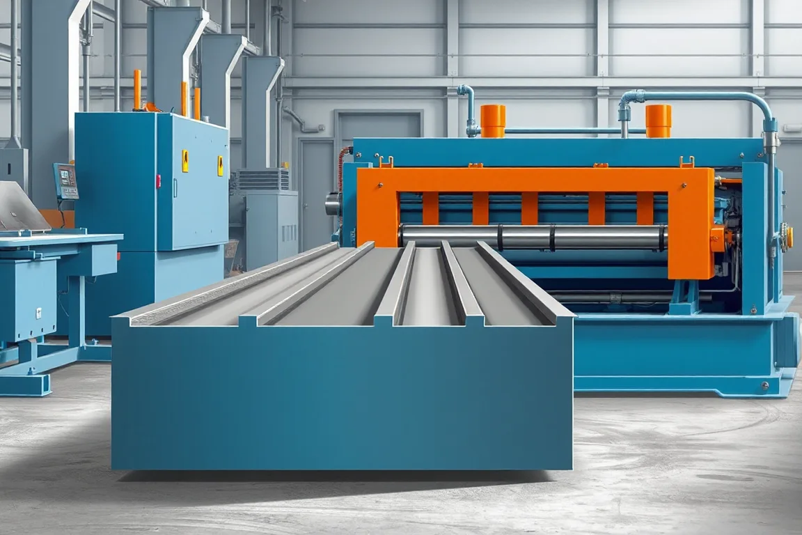
A floor deck roll forming machine produces profiled steel sheets used in a specified floor construction. The equipment must reproduce the ribs, pans, side joints and other features that define the deck product, then deliver the required lengths in a condition suitable for identification, transport and installation.
The first decision is what the floor deck is intended to do. A sheet used as permanent formwork and a deck designed to participate in a composite slab are not interchangeable manufacturing targets. Their drawings, feature requirements and qualification evidence should be established before selecting the production line.
What type of floor deck will the factory make?
Non-composite form deck provides the specified formwork role in the floor arrangement. Composite deck includes the geometry and surface features used by its approved slab design. The manufacturing brief must identify the exact family rather than treating every ribbed floor sheet as a composite product.
Also distinguish the deck from the complete floor system. Reinforcement, concrete, supports, connections, openings and construction sequencing are not supplied simply by buying a deck former. The line makes a defined component whose use follows the applicable engineering design.
Which cross-section dimensions matter?
Provide the full profile, including repeating ribs and both terminal edges. Rib depth, pitch, pan dimensions and bend geometry establish the main section, while side joints govern the relationship between adjacent sheets. Overall width and effective cover should be stated separately.
- Rib and pan geometry, with clear measurement datums.
- Side-lap or interlocking-edge construction.
- Required embossments, tabs, vents or other product features.
- Material grade, base-metal thickness and coating.
- Finished length range and end condition.
- Bundle orientation, identification and handling requirements.
A regional deck name or nominal depth is not a complete tooling specification. Similar-looking products may have different side joints or rib shapes. Use controlled drawings and representative mating samples to resolve those differences before tool manufacture.
How does the line turn coil into floor deck?
The proposed route combines coil handling, entry guidance, progressive profile development, required feature operations, length cutting and supported discharge. Embossing or other features must be coordinated with the forming sequence where they are part of the selected deck.
- Load and identify the approved coil.
- Present the strip consistently to the forming path.
- Develop the repeating ribs and terminal edges through successive passes.
- Create the specified product features in the agreed sequence.
- Cut the deck to the released order lengths.
- Support, inspect, identify and stack accepted sheets.
Ask for the actual layout and process sequence. A feature placed before forming has different tooling and referencing questions from one produced after the section is developed. The supplier should explain how the required final geometry is controlled.
How should the material envelope be described?
List grade, thickness, strip width and finish as combinations associated with each deck profile. Forming a deeper or more complex section in a different grade is not equivalent to merely changing a thickness setting. The trial plan should include the combinations relevant to ordinary and demanding production.
Keep base-metal thickness separate from coating measurements and retain coil identification with finished bundles. If a later side-lap or straightness issue appears, the manufacturing team needs to compare material, profile setup and handling conditions with the approved reference.
Coating requirements also affect inspection. Examine bends, embossed areas where present and cut edges using the actual material. Do not substitute an appearance check for the material documentation required by the product specification.
What is the role of embossments and other features?
Where a composite-deck design includes embossments, their shape, depth, position and repeat pattern belong in the controlled drawing. They should not be treated as generic decorative marks or changed casually to suit available tooling. The equipment needs to reproduce the features associated with the selected product design.
Tabs, venting or other optional details likewise require their own scope. Specify whether they are needed for every sheet, selected orders or a separate deck variant. Their production method can affect tooling, controls and inspection, so they should not be added as an undefined future capability.
Manufacturing inspection verifies that those features match the specification. It does not independently establish the structural behavior of a slab or replace the product's required engineering evidence.
How should side joints be checked?
Assemble several production-intent sheets using the side-joint arrangement specified for the deck. Check effective cover, engagement and the condition of the terminal ribs after normal handling. A sheet can have acceptable central ribs while one edge prevents correct assembly.
Measure the end and middle portions of the joint. Cutoff damage or handling distortion may create a local problem that a short sample from the center misses. Record whether assembly requires unplanned forcing or reshaping.
Keep the manufacturing fit check distinct from the method used to connect deck on a project. The attachment type, spacing and installation procedure belong to the floor design and should not be inferred from a successful loose-sheet fit.
Dedicated deck tools or a flexible product range?
A dedicated line can suit a stable high-volume profile. A changeable or multi-profile arrangement may support a wider catalogue, but the physical changes should be clear. Different rib pitches, depths and side joints can require substantial tooling changes rather than a simple width command.
Request a configuration matrix listing roll tools, guides, feature tools, cutoff components and discharge settings for each deck. Demonstrate a relevant change through to accepted sheets, then recover the original product. Include inspection and startup scrap in the comparison.
Future profiles should be reviewed against the actual machine envelope. Sharing the word deck does not make unrelated sections automatically compatible with the same stands, drive or cutting arrangement.
Why is discharge support important?
Floor-deck sheets can be long and require a coordinated path through cutting, inspection and stacking. Support must suit the section and length range without damaging ribs or terminal edges. A former that runs acceptably but cannot clear finished sheets at the required rate is an incomplete production solution.
Define nesting direction, stack height, separation requirements and lifting arrangements. Confirm that a packed stack remains identifiable and that sheets can be removed without unacceptable damage. Handling trials should use representative lengths rather than only short demonstration pieces.
How should practical output be calculated?
Compare accepted deck area or sheets over a defined order, including the actual lengths and profile changes. Use effective cover when calculating nominal supplied area. Input coil width and overall sheet width are different quantities and should not be substituted for installed coverage.
For arithmetic only, 200 accepted sheets, each 4 metres long and 0.75 metre effective cover, represent 600 square metres of nominal deck coverage. This example is not a production rating or a construction takeoff; it excludes project-specific overlaps, openings and waste.
Record coil changes, cutoff cycles, inspection, rejected pieces and stack removal. Those activities determine how a line serves actual orders, whereas a steady strip-speed demonstration describes only part of the process.
What belongs in the quotation scope?
Include coil loading, payoff, forming tools, required feature equipment, cutting, takeoff and stacking. Add inspection aids, controls, training and commissioning responsibilities. Clarify whether edge closures, pour stops and other floor accessories are purchased or made on separate equipment.
Compare the same profile and material matrix across suppliers. A package for one plain form-deck section should not be compared directly with a multi-profile composite-deck line containing additional feature and handling equipment.
What should acceptance demonstrate?
- Approved ribs, pans, terminal edges and effective cover.
- Required features measured against the controlled drawing.
- Length, straightness, end condition and coating observations.
- Assembly of several adjacent sheets.
- Production of representative short and long orders.
- A required profile change and repeatable recovery.
- Identified packed stacks and accepted-output records.
Retain the trial material details, setup and samples. They establish a practical production reference and make future deviations easier to investigate.
Frequently asked questions
Is all floor deck composite deck?
No. The intended function and approved product design determine whether the deck is composite or non-composite. Specify the exact section and features before selecting machinery, and keep the complete slab design separate from machine capability.
Can a roof-deck machine make floor deck?
Only where the required floor profile, material and features are supported by its configuration. Similar corrugations do not establish compatible tooling or equivalent use. Review both drawings and the necessary changes.
Can embossments be added later?
They require a defined engineering and tooling review. Their geometry and relationship to the profile must match the intended deck design. Treat them as a controlled product feature, not a universal upgrade.
Why measure effective cover?
It describes the useful width after adjacent sheets engage. Overall sheet width includes the joint geometry, while input strip width includes material developed into the ribs. Keeping these quantities separate avoids misleading area calculations.
Does the line also make floor accessories?
Only if their separate profiles and operations are included. Pour stops, closures and other accessories may need folding, cutting or different roll tools. Define that boundary in the equipment package.
What is the best enquiry package?
Send the deck drawing, material combinations, feature details, length mix and side-joint references. Add stack and identification requirements. This supports a comparison based on complete saleable deck production.

Continue your research
- Floor Deck Roll Forming Machines
- Roof Deck Roll Forming Machine
- Composite Deck Roll Forming Machine
- B Deck Roll Forming Machine
- N Deck Roll Forming Machine
- H Deck Roll Forming Machine
- How Floor deck roll forming machine Works
- How To Choose a Floor deck roll forming machine
- Floor deck roll forming machine Price: What Affects the Cost?
Configuration & specification inputs
Match the configuration to your section drawing, material and production requirements.
| Parameter | Requirement / confirmation needed |
|---|---|
| Profile geometry | Floor-deck ribs, pans, terminal edges and defined effective cover |
| Material | Specified deck grade and coating linked to coil and bundle records |
| Thickness & grade | Approved base-metal thickness and grade combinations by profile |
| Process route | Coil handling, rib and edge development, required features, cutoff and stacking |
| Cutting | Preserve rib and side-joint geometry over the required length range |
| Output | Accepted sheets and nominal cover area including changes and stack removal |
| Electrical supply | Confirm utilities for the selected deck tools, feature equipment and handling scope |
| Acceptance | Measure section and features, assemble adjacent sheets and inspect representative packed stacks |