
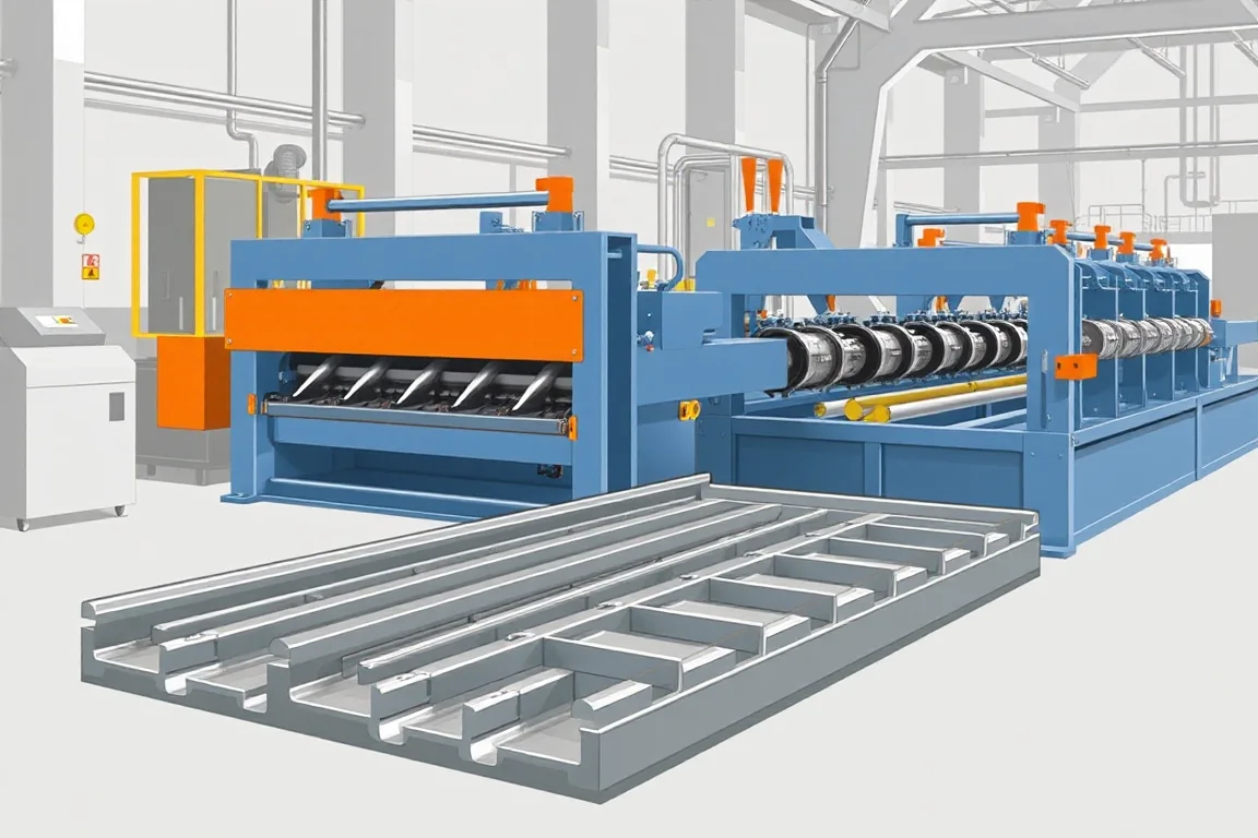
A metal deck roll forming line is the complete production arrangement that converts coil into identified, stackable deck sheets. It includes more than the forming stands: coil handling, profile tools, optional feature operations, cutting, takeoff, inspection and order control must work as one route.
This broader line perspective is useful when a factory intends to supply several deck families or substantial project orders. The objective is not the highest isolated forming speed. It is dependable delivery of the required profiles, materials and lengths with repeatable changes and a handling system that keeps up.
Which deck families should the line cover?
Separate roof deck, non-composite floor deck and composite deck in the product matrix. Each family needs its controlled cross-section, side joint, material combinations and features. Products with a similar rib depth can still differ significantly at the terminal edges or in embossing requirements.
Add specialized variants only where they are part of a defined commercial plan. Vented, perforated, cellular or otherwise assembled products can require additional operations and components. A broad catalogue is useful only when the equipment scope explains how each product will actually be manufactured.
How should the production matrix be organized?
Use one row for each approved configuration rather than a loose list of maximum capacities. Identify profile, material, thickness, input width, features and length range together. This prevents an apparently generous envelope from implying combinations the proposed machine has never been designed to make.
- Product: drawing reference, profile family and side-joint type.
- Material: grade, thickness, coating and strip width.
- Features: embossments, slots, vents or other required operations.
- Order: length mix, batch size and identification needs.
- Handling: stack format, removal method and dispatch sequence.
- Changeover: tools, settings and inspection needed for the next configuration.
Use this same matrix when comparing suppliers, planning trials and training operators. It provides a common reference across the commercial and production sides of the project.
What should the coil-entry package include?
Define the coil envelope and the method used to bring coils to the payoff. Loading, storage, threading and strip presentation need space and a safe operating plan. The line layout should show those activities rather than beginning at the first forming stand.
Consider the frequency of material and width changes. A factory with short varied orders may spend a substantial portion of its time preparing coils, while a long-run operation may prioritize continuity and efficient coil replacement. Compare the actual workflow and staffing assumptions.
Any preparation equipment should have a clear purpose tied to the incoming material and forming route. Do not add or omit a function solely because it appears on another line's equipment list.
Which forming arrangement best fits the product mix?
A dedicated route concentrates on one profile family. Changeable-tool or raft-type arrangements support a wider range through planned transitions. Multi-level or multiple-path equipment can reduce some tooling changes, but shared feed, drive or discharge equipment may still mean one product runs at a time.
Ask how the complete line changes from one deck to another. Roll tools are only part of the transition: guides, feature tools, cutoff components, controls and stacking settings may also change. Include the recovery of an accepted sheet in the comparison.
Choose flexibility that matches expected orders. Paying for many theoretical configurations is less useful than a practical route for the profiles the factory will regularly sell.
Where should feature-making sit in the route?
Embossments, vents, slots or other details need a defined relationship to the finished ribs and ends. Their position in the process should be explained by the equipment proposal. Features made before forming may need to account for subsequent development, while later operations need access and support for the shaped section.
Review feature combinations, not just individual examples. The required pattern and frequency can influence tooling duty and the operating cycle. A demonstration with features disabled does not establish output for the finished commercial product.
Keep each feature tied to its controlled product drawing. This is especially important when a shared line makes both plain and composite deck, because a convenient production setting should not silently alter the approved product definition.
How should cutting be integrated?
Compare the proposed cutting arrangement with the required profiles and length mix. The important result is an accepted sheet end produced at a useful complete-line cycle. Different cutting concepts can have different support, control and maintenance requirements, so evaluate the actual proposal rather than choosing by name alone.
Inspect local rib and side-joint condition after cutting. Test short products with frequent cuts and long products requiring extended support. A line can perform well on one while exposing a limitation on the other.
Clarify how length changes and order transitions are controlled. The operator should be able to identify the last sheet of one order and the first sheet of the next without relying on informal counting.
What does the discharge system need to accomplish?
Takeoff must support the full sheet, preserve functional edges and clear the cutting area at the required rate. Stacking should match the profile's nesting behavior and the customer's delivery format. Draw the movement of both individual sheets and completed bundles.
Include access for inspection, rejected sheets and stack removal. A layout that has no practical route for a completed bundle can interrupt an otherwise capable former. The design should also avoid mixing different lengths or material specifications during order changes.
Test the proposed handling with representative products. A compact short sheet is not a sufficient demonstration of the longest or most vulnerable deck in the catalogue.
How should controls support the order workflow?
Define the required production information: profile, material, length, quantity, features and bundle reference. Identify how it is entered, checked and associated with physical output. A clear order screen is useful only if the line and labels preserve the same information through dispatch.
Consider interrupted orders, coil replacement and rejected sheets. The counting logic should distinguish produced pieces from accepted pieces and allow the operator to complete the intended quantity without obscuring scrap. These routine situations deserve a demonstration during commissioning.
Keep machine recipes linked to controlled configuration references. A stored name such as floor deck is too vague if several drawings or embossment patterns exist under that family.
How can the real production constraint be identified?
Run a representative order and record time spent in coil preparation, forming, feature-making, cutting, inspection and stack removal. The limiting stage may change with profile and length. Improving one stage without matching the others can simply move the waiting time elsewhere.
Use accepted sheets and nominal cover area as the output measures, with the operating conditions stated. Report changes and rejects separately. A brief uninterrupted run should not be extrapolated into a shift rate without accounting for the normal work around it.
For planning, compare at least a long repeat order and a shorter mixed order. The first reveals sustained production behavior; the second reveals changeover and order-control demands. Both can matter to the same business.
What should the investment comparison separate?
Separate common line equipment from profile-specific tools and optional automation. Common items can include coil handling, drives, controls and parts of the discharge system; profile-specific items can include rolls, embossing tools and cutoff components. The exact boundary depends on the design.
Also identify site preparation, utilities, lifting arrangements, training, commissioning and inspection aids. Future profile additions should state whether they fit the existing envelope or need substantial changes. This makes the initial and expansion costs more understandable.
What should a complete-line acceptance trial include?
- Confirm the product matrix, materials and controlled drawings.
- Run representative configurations with all required features active.
- Measure sections, joints, features, lengths and end condition.
- Assemble adjacent sheets where required for fit verification.
- Demonstrate order changes, coil replacement and profile recovery.
- Count, label and remove normal finished stacks.
- Record accepted output, rejects, stoppages and unresolved deviations.
The trial should leave the production team with usable settings, reference samples and procedures for the actual line. A series of isolated machine demonstrations is less valuable than evidence that the connected route delivers the intended orders.
Frequently asked questions
What is the difference between a former and a complete line?
The former develops the profile. A complete line also manages the material, required features, length production, collection and order output. Confirm the supply boundary because sellers may use the terms differently.
Does a double-level arrangement double output?
Not automatically. It may provide two profile paths while sharing feed, drive or discharge equipment. Simultaneous operation must be explicitly supported. Evaluate the actual scheduling benefit rather than inferring capacity from the number of levels.
Can roof and floor deck share one line?
A configured line can cover specified products from both families. The profile, material, side-joint and feature requirements determine the necessary tools and changes. Review a complete matrix instead of assuming all deck is equivalent.
Which speed should be compared?
Compare accepted finished output for the same order and included operations. Strip speed is useful context, but feature-making, cutting, changes and stacking determine the practical production result.
Should automation be installed immediately?
Base the choice on order mix, staffing, quality and handling demands. Identify the stage that constrains useful output and the interfaces needed for future additions. More automation is not automatically a better fit for every factory.
What should the first enquiry contain?
Provide the product matrix, drawings, materials, length mix, expected orders and available layout. Add feature, identification and stack requirements. This allows the proposal to address a complete deck-manufacturing workflow.

Continue your research
- Floor Deck Roll Forming Machines
- Floor Deck Roll Forming Machine
- Roof Deck Roll Forming Machine
- B Deck Roll Forming Machine
- N Deck Roll Forming Machine
- H Deck Roll Forming Machine
- How Floor deck roll forming machine Works
- How To Choose a Floor deck roll forming machine
- Floor deck roll forming machine Price: What Affects the Cost?
Configuration & specification inputs
Match the configuration to your section drawing, material and production requirements.
| Parameter | Requirement / confirmation needed |
|---|---|
| Profile geometry | Controlled matrix of roof, form and composite deck configurations |
| Material | Product-specific grade, thickness, coating and input-width combinations |
| Thickness & grade | Define approved combinations rather than unrelated line maxima |
| Process route | Coil entry, configured forming, feature-making, order-based cutting, inspection and stacking |
| Cutting | Coordinate profile support, order transitions and actual short/long length mix |
| Output | Accepted finished orders including setup, coil changes, features and stack clearance |
| Electrical supply | Confirm connected-load and utility requirements for the complete integrated route |
| Acceptance | Run representative orders with features active, demonstrate changes and verify counted labelled stacks |